Obviously I can't speak for anyone else but from what I've gathered from others as well as my experience setting up my own F6 is that >5.1V is necessary when using IRFP fets and that 9.1V works fine. Someone said it was stupid but they didn't really give any reason why..
Yup, but now there seems to be conversation on not only which voltage, but more confusing which mA version of that voltage and what resistor chages one may need to make depending....cheapest part in the whole build giving me headaches! lol
Russellc
Russellc
Yup, but now there seems to be conversation on not only which voltage, but more confusing which mA version
of that voltage and what resistor chages one may need to make depending....cheapest part in the whole build giving me headaches!
You could even use a high performance shunt voltage regulator in place of the zener. This part can use any current from 1mA-100mA.
Of course it won't fit on the stock pcb. Just remember that the pot takes a couple of mA as well.
https://www.fairchildsemi.com/datasheets/TL/TL431.pdf
In any event you want enough gate voltage, and enough current for the wattage of zener that you use, Pz/(10*Vz) or more.
Last edited:
All I can add to this discussion is I used 1 watt 9.1 zener diodes and left everything else just as the F6 schematic and had no problems and it biased up nicely. 1 watt is overkill but the price is not that much higher. No resistor changes that are being discussed. Worked for me.
1N4739A-T Diodes Incorporated | Mouser
1N4739A-T Diodes Incorporated | Mouser
You could even use a high performance shunt voltage regulator in place of the zener. This part can use any current from 1mA-100mA.
Of course it won't fit on the stock pcb. Just remember that the pot takes a couple of mA as well.
https://www.fairchildsemi.com/datasheets/TL/TL431.pdf
In any event you want enough gate voltage, which means enough current for the wattage of zener that you use, Pz/(10*Vz) or more.
I'm using the zener, any ideas along those lines?
Much appreciated,
Russellc
use Papa's resistor values and put any sort of power/milliamperage zener you can find
no brainer
no brainer
I'm using the zener, any ideas along those lines?
If it's a 400mW zener, use a 2.2k, 0.5W resistor for R7. That allows about 5mA in the zener,
which is only about 10% of the maximum rated zener current. I wouldn't go any lower than that.
Also remember that under heavy load, the 24V supply will drop, reducing the zener current even more.
The large cap in the gate circuit will help mitigate this, though you don't want the zener to "drop out".
Last edited:
If it's a 400mW zener, use a 2.2k, 0.5W resistor for R7. That allows about 5mA in the zener,
which is only about 10% of the maximum rated zener current. I wouldn't go any lower than that.
Also remember that under heavy load, the 24V supply will drop, reducing the zener current even more.
The large cap in the gate circuit will help mitigate this, though you don't want the zener to "drop out".
Thank you, and ZenMod also. My transformer is 500 VA 18+18 Hopefully that will help with the reduced currents under heavy load? I think I am fine based on everyone's feedback. Thanks everyone!
I still need the cases (store is out right now, and so is my play money) before I can finish...😱
Russellc
This part can use any current from 1mA-100mA.
Of course it won't fit on the stock pcb. Just remember that the pot takes a couple of mA as well.
https://www.fairchildsemi.com/datasheets/TL/TL431.pdf
I used the TL431 on the JFET version, as they require less Vgs.
I used the TL431 on the JFET version, as they require less Vgs.
Probably I'll use the TL431 in the F6 that I'm building, since I need custom pcbs anyway because of the
size/shape of the two (mono) chassis.
Last edited:
Obviously I can't speak for anyone else but from what I've gathered from others as well as my experience setting up my own F6 is that >5.1V is necessary when using IRFP fets and that 9.1V works fine. Someone said it was stupid but they didn't really give any reason why..
The R7,R8 + the trimmers form a 1/3 resistor divider network.
If you have, lets say 25V power supply rail voltages, you will get 25/3=8.33V from your divider.
Now the no brain question is, what purpose does the 9.1V zener serve in that circuit??????????
Change the R7,R8 value as suggested by rayma.
Or, use a different zener.
Like 6.2V, which already can give so high bias current to the output stage that you can adjust the whole thing to a complete melt down if you wanted - including your speakers if/when one of the mosfets blows before the other...
Also, make correction to the BOM of diyAudio F6, according these components.
The R7,R8 + the trimmers form a 1/3 resistor divider network.
If you have, lets say 25V power supply rail voltages, you will get 25/3=8.33V from your divider.
Now the no brain question is, what purpose does the 9.1V zener serve in that circuit??????????
Most likely your 25V power supply will have some ripples. The purpose of the zener is to ensure constant voltage for the bias. If you only used a resistor network, the ripple would propagate into the bias setting, and also the offset-setting.
At least, thats the way I understand it 🙂
Last edited:
Most likely your 25V power supply will have some ripples. The purpose of the zener is to ensure constant voltage for the bias.
If you only used a resistor network, the ripple would propagate into the bias setting, and also the offset-setting.
Yes, though there's a strong RC filter after the zener. Also, if there is too little zener current and thus no regulation,
the bias will vary with the line and load. This may be why some have had offset/bias drift problems.
Thanks for all the great support.
Indeed, good point. 🙂
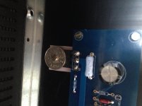
Anyway, I finished my F6 today. Compared to some of the other builds I've seen here it is not spectacular in any way, but I was quite happy to discover that one Norwegian Krone, the smallest coin in the Norwegian currency, works perfect at a washer to hold the FETs down. They are produced with a hole in the middle.
I've hooked it up to my rather large diy Voxativ transmission lines and they love each other! We had a few friends over already, Diana Krall dropped by to sing Besame Mucho, Lisa Ekdahl sung about a nature boy. Alfred Janson then came along with his accordeon and told us not to forget him (Ne me quitte pas). Eva Cassidy did an acoustic cover of wayfaring stranger, and there goose bumps all over the place! An amazing amplifier.
I took me quite a while to finish this project, and I own thanks to many people in this great forum. Hannes, Semisouthfan, Spencer. Super big thanks to 6L6 for the build guide, it was very useful. And of course Nelson Pass for sharing his knowledge 🙂
Yes, though there's a strong RC filter after the zener. Also, if there is too little zener current and thus no regulation,
the bias will vary with the line and load. This may be why some have had offset/bias drift problems.
Indeed, good point. 🙂
Anyway, I finished my F6 today. Compared to some of the other builds I've seen here it is not spectacular in any way, but I was quite happy to discover that one Norwegian Krone, the smallest coin in the Norwegian currency, works perfect at a washer to hold the FETs down. They are produced with a hole in the middle.
I've hooked it up to my rather large diy Voxativ transmission lines and they love each other! We had a few friends over already, Diana Krall dropped by to sing Besame Mucho, Lisa Ekdahl sung about a nature boy. Alfred Janson then came along with his accordeon and told us not to forget him (Ne me quitte pas). Eva Cassidy did an acoustic cover of wayfaring stranger, and there goose bumps all over the place! An amazing amplifier.
I took me quite a while to finish this project, and I own thanks to many people in this great forum. Hannes, Semisouthfan, Spencer. Super big thanks to 6L6 for the build guide, it was very useful. And of course Nelson Pass for sharing his knowledge 🙂
Attachments


I also finished my F6 today and I'm very happy though I have not had enough time to listen to it yet.
I biased it at 0.6v, about 1.27A as the heatsink temp was already at 55c in stand by after an hour.
Thanks Mr. Pass!
-Alex
Sent from my iPhone using Tapatalk
I'll do more pics tomorrow, anyway is quite standard, 400VA, 88.000um x bank,.
I inserted the Soft Start Circuit but something went wrong: the relay did't switch so the 5w resistors were cooking.
I removed it and the PSU charges and discharges very well also without it.
-Alex
Sent from my iPhone using Tapatalk
I inserted the Soft Start Circuit but something went wrong: the relay did't switch so the 5w resistors were cooking.
I removed it and the PSU charges and discharges very well also without it.
-Alex
Sent from my iPhone using Tapatalk


Here there are the inside pics. The bridges are positioned on the back of the front plate. The case is 4U Deluxe; after 2h the heatsink temp is 53C, with an ambient temp of 28C. The bias is 0.6V across R2. I think that the 4U case is not enough to bring the bias to 1.55A...
-Alex
Sent from my iPhone using Tapatalk
- Home
- Amplifiers
- Pass Labs
- The diyAudio Firstwatt F6