I think this is an excellent idea and strongly recommended for this project! Did we decide on a controller yet? Who are our AVR or PIC experts out there? (yes, I ignored the Motorola/ON Semi stuff - sorry)
mlloyd1
mlloyd1
R. McAnally said:
I think digital pots should be used throughout for attenuation.....you could incorporate a digital "sleep" mode when no controls have been touched for a few seconds, for minimal noise.
whoa
mlloyd1, that looks like a lot of gain. 2 diff pairs in a row? and global feedback, hmmm... though i will add that i am not completely against feedback, i am still considering both discrete and IC opamps. maybe i am just reading your schematic wrong...
i'm using a AVR controller btw. i'm not too worried about that part, it's just software after all.
harry, what "Scheißesturm"? things look pretty calm to me now, other than that brief diversion which thankfully is now behind us.. anyway don't let the others discourage you, i still want to hear everything you have to say. 😀
does someone want to answer my question about the Metaxas circuit? 😛
If no one makes a suggestion/path now for the design we will end up with a motherboard where you can exchange :
1)cpu type
2)display type
3)controll/keys type ... I prefer Racon8 and bourns encoder
4)power supply
5)line filter
6)opamps/amps whatever
7)relay/solidstate switches
8)type of attenuator
9)connectors
10) ... Maybe tube instead of solidstate devices
11) All parts should be welded on the board to remove thoughts about silver versus nonsilver tin. ... ohh nooooo!!! Also the mainboard should be exchangeable ... teflon versus FR4 versus AIR ... conductor .. gold versus silver versus mercury versus paladium
Okay i shut up!
Sonny
Re: our much loved guru Harry has some ideas
Come on H.H., don't get off the train yet. Things are starting to get good!
mlloyd1
Come on H.H., don't get off the train yet. Things are starting to get good!
mlloyd1
HarryHaller said:Well I was going to offer some suggestions on changes to the Borbely topology .....
H.H.
don't fret sonny
if you go back and read my updated requirements list, i think it rules out most of your insane design permutations. 😛
as for the gain stage itself, i'm open to plenty of suggestions for now. we're in the brainstorming phase so no holds barred! actually if i see something i really don't like i'll probably shoot it down anyway... j/k... sorta...
Hey! We are getting off track here.
The schematic Peter (H Potter) posted was a good starting point.
Harry is right. Both he and I were were thinking alont the same lines about using the Borbely as a basis for a really outstanding design with mosfets and improved followers but as usual most miss the point and introduce a bunch of irrelavent nonsense to confuse matters.
Let us explore the possibilities of this topology and see if it fits the criteria for the design. We don't have the basic topology down yet and secondary details like servos volume controls are being thrown in.
Then the moderator has to step in...... sounds like the begining of a cluster f#*! to me.
Jam
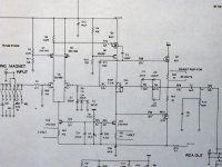
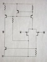
Talking about Metaxa again, I'm not sure about the connection. Maybe R4 to ground and negative input to the right side gate? Last schematic from me today. Metaxa looks similar to the buffer from Pass Labs crossover (picture below) in certain ways. Could these two be combined in one, with negative and positive outputs and no need for coupling caps?
I guess I placed the picture upside down.🙁
I guess I placed the picture upside down.🙁
Attachments
ok jam sounds good.
i have no objections to the boberly so let's tweak it to death (metaphorically speaking of course).
as for the diversions, the DC servo was my bad. i was only bringing it up because every proposed circuit has been capacitor coupled, but my intial requirements list called for DC coupled circuits only. i guess that went out the window though. 🙁
the remote control comments were legitimate as it came from lingering discussion on the topic a few pages ago, but since we want to concentrate on gain stages now let's put that aside. i will get a web page up soon so we can organize the different ideas that have been thrown up there.
btw, no one commented on how MANY active stages we'll have, i.e. if we want to buffer the input and/or distribute gain. that is sort of relevant i think as it determines the implementation, although a good gain stage is still a good gain stage however it's used. any thoughts?
Re: whoa
Hi dorkus:
We gotcha' lower gain right here: add some source and emitter degeneration! You're gonna have to rework compensation, bias points, etc. anyways. The RIAA shaping is done in the feedback loop for this design, so a fair amount of open loop gain is needed. Of course, if you go passive, constraints can change. Also, Leach makes some comments about the second diff stage cancelling some effects of the first one in the paper.
Where's our simulator? Sonnya, are you out there? 🙂
So, do we have a requirement on the table for the discrete gain blocks having no global feedback?
mlloyd1
dorkus said:mlloyd1, that looks like a lot of gain. 2 diff pairs in a row? and global feedback, hmmm......
...
Question?
Question?
Why after it was decided on a balanced approach is everyone posting single-ended designs?
Question?
Why after it was decided on a balanced approach is everyone posting single-ended designs?
Re: Question?
hmm, well i thought balanced outputs were optional but some people motioned to make them a requirement, given that they use balanced gear and a lot of the Pass stuff is inherently balanced anyway. i think we can still look at single-ended as design exercises, but you are right, we should probably stick to one or the other. however if someone comes up with some miracle single-ended circuit that blows everything away...
jam said:Question?
Why after it was decided on a balanced approach is everyone posting single-ended designs?
hmm, well i thought balanced outputs were optional but some people motioned to make them a requirement, given that they use balanced gear and a lot of the Pass stuff is inherently balanced anyway. i think we can still look at single-ended as design exercises, but you are right, we should probably stick to one or the other. however if someone comes up with some miracle single-ended circuit that blows everything away...
Re: Re: whoa
absolutely not. i do have requirements, but no blanket rules for a design decision at that level. in fact i am willing to look at discrete op amps at well. i was just mentioning the feedback because i figure most people turn to discrete over IC because they want to avoid the nasties associated with massive amounts of feedback, among other things. our discrete designs don't even have to be Class A for that matter, altho i'm sure everyone will cry foul if we even try to do something AB.
mlloyd1 said:So, do we have a requirement on the table for the discrete gain blocks having no global feedback?
absolutely not. i do have requirements, but no blanket rules for a design decision at that level. in fact i am willing to look at discrete op amps at well. i was just mentioning the feedback because i figure most people turn to discrete over IC because they want to avoid the nasties associated with massive amounts of feedback, among other things. our discrete designs don't even have to be Class A for that matter, altho i'm sure everyone will cry foul if we even try to do something AB.
A buffer before the volume control might be a good idea if the impedence of the volume control is low and the source components have a high output impedence. It could be left as an option on the board.
I would like to request Harry to share his thoughts on improving the basic topology since I think he is on the right track. At this point anyone should be free to suggest changes (constructive) and ask questions so that all possibilities are covered.
Jam
I would like to request Harry to share his thoughts on improving the basic topology since I think he is on the right track. At this point anyone should be free to suggest changes (constructive) and ask questions so that all possibilities are covered.
Jam
ok. let's work on a single gain stage for now. if we decide to distribute the gain later between input and output stages (i think it's a nifty idea) then we can make the necessary adjustments at that time. we may not need it anyway if we go with a higher-impedance volume control, at the cost of a little noise performance.
Let's see.........
Let's look at the topology I am talking about.
Balanced or single-ended in and balanced or single-ended out. We can use global feedback if we want or not and has the characteristics of a single ended topology. The output buffer should isolate it from difficult loads which could cause gain variations in a simple differential amplifier.
In other words a balanced single-ended design that should fit most peoples needs.
Any other ideas?
Jam
P.S. Besides if anyone wants to wire it up as a single-ended design , they can because the differential does the necessary phase inversion....and then there is the possibility of a phase reversal function...... the list goes on.
Um, a question in passing...
I just quickly went back through the posts and, granted, I'm at work and my attention is divided, but has anyone decided how much gain the preamp is supposed to have? If so, I missed the post. If not, it seems like one of those Most Essential specs that should be part of the discussion.
Given that it's to be a line stage only, I'm assuming that a lot of people will be using it for CDs, etc. but others may need an extra bit of <i>oomph</i> for phono or possibly tape (some had perfectly reasonable output levels, others were pretty puny, to say the least).
What are you shooting for? 6dB? 12? 20?
The answer will tell you a lot about what topology you'll need to consider. If all you want is 6dB, you can easily leave out cascodes. If, perchance, you're going for 20-30dB, then cascodes may need to be part of the discussion. I don't recall how much gain the Borbely circuit has (incidentally, I kinda like the idea of the dual JFET for a gain stage), but the Pearl is gonna have a whackin' huge amount of gain for a line stage once you remove the RIAA filter, something on the order of 60 or 70dB. Those who are fond of lots of feedback will have a field day burning that back down to, say, 15dB closed loop gain, but those who think in terms of more modest amounts of NFB will blanch at the thought.
Grey
They work but are harder to get right. There seems a fondness for single-ended designs in this forum.
I should add that a lot of Nelson Pass's designs (the X-amps) are complementary.
Jam
I should add that a lot of Nelson Pass's designs (the X-amps) are complementary.
Jam
- Status
- Not open for further replies.
- Home
- Amplifiers
- Solid State
- The diyAudio.com preamp project!