
You know, it's a funny thing...I was working on a PC board this afternoon before coming to work and my mind travelled back to the first board I made. I had numerous questions about what was going on and no one to ask them of. Fortunately, the circuit worked first time out. Great!
Starting a project from scratch is a wonderful way to learn about all the steps involved; original concept, consideration of various ways to approach the problem, prototypes, ironing out the bugs, false starts, wrong turns, things that go wrong that you didn't expect, new solutions followed by new problems--but finally, if you are persistant enough, you've got something to show for your effort and, if you worked with it long enough and hard enough, it's hopefully something to be proud of.
That's not to say that you'd solve the same problem the same way next year. If everything is going right, you might have learned something in the meantime that leads you to a better, more elegant solution. I know that first circuit board of mine had a lot of chips on it. I wouldn't be caught dead building a crossover that way now--but it did what it was designed to do and I was happy with it for a long time.
Perhaps...just perhaps some people have nothing better to do with their time than tear other people down who are trying to accomplish something. If so, that's pretty sad. I might or might not agree with any or all of the engineering decisions being made in this thread. That's irrelevant. The point is that some people are trying to get some things done, and there are others who are swaggering around acting pretty obnoxious, but contributing little, if anything, to the central purpose of the thread.
It's a learning process, folks. If they want to do it by committee, then let them. Perhaps the thing they learn is that groups tend to bog down. On the other hand, who knows?, they might just form a skunk works and leave your butts on the side of the road with the taste of dust in your mouth.
I'm going to say this once, just once, nice and clear for those who didn't get the message in another thread: If you don't intend to contribute to the thread, get out and leave them alone. Snide remarks, back-seat driving, unasked-for criticism (particularly when no suggestions for making it better are forthcoming), and general immature bullying aren't going to fly.
I'm wearing my moderator's hat, and I'm watching.
Grey
I apreciate your comments Grey, but they also don't introduce anything constructive to that thread. On the contrary they will actually slow the progress of the preamp design by further unnecessary comments and ego fighting. If I don't like something I just ignore it or turn it into a joke. Sooner or later the interested parties would get it.
I rather value Harry's and Jocko's comments, because maybe sometimes out of place, they bring practical knowledge we all could use. (at least I have already used some of their tips).
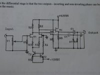
Here is another design. I kind of like its simplicity. Comes from Kostas Metaxas and was originally designed in 1979. I lost the link but have more info.🙂
I rather value Harry's and Jocko's comments, because maybe sometimes out of place, they bring practical knowledge we all could use. (at least I have already used some of their tips).
Here is another design. I kind of like its simplicity. Comes from Kostas Metaxas and was originally designed in 1979. I lost the link but have more info.🙂
Attachments
i don't think grey was specifically targetting you or harry or jocko, hp, but was addressing some earlier snide comments that went around. i too am pretty tolerant, but it would be nice if people stuck to constructive comments as he says. i think the nay-sayers have lost interest in the thread by now anyway, so we should be good to go from here on out.
Yes, but the signal to noise ratio could be much, much improved. One helpful post does <i>not</i> excuse fifteen pointless or insulting ones and judging from the e-mail I'm getting, the people who find Harry, Jocko, et. al. amusing are a very tiny minority, indeed. A noisy, very vocal minority, but tiny.
For them to vent their egos at others' expense is inexcusable and just plain bad manners.
Grey
For them to vent their egos at others' expense is inexcusable and just plain bad manners.
Grey
So, we have three schematics, no comments yet. I kind of like the last one. Maybe there is a room for improvement here (signal to noise)?😉
Grey,
As someone who lurks and learns, and is non-vocal generally, I'd say that Jocko seems to leave around enough well gnawed bones to just about earn his keep.
Sure, Harry don't keep him on a tight enough leash, and should probably muzzle him more (and take a plastic bag him to pick up his sh1t).
Still, although he may belong in the doghouse, I don't think he deserves to be put down (I mean that in the veterinary sense, and the veterinary sense only).
Call me soft.
Jake
i like the last one a lot too. i like the emitter follower output stage, my analog skills are weak (i slacked too much in that class, it was senior year after all) but i suspect the circuit will be pretty linear and have good drive capability. are those generic mosfets? i'm assumming we're going with mosfets instead of bipolars, although i rather like the sound of a good bipolar amp... (preamp might be different matter tho)
so i guess there's no way (topology, hack, or otherwise) to get a DC coupled version of these lovely single-ended class A circuits huh? 🙁
so i guess there's no way (topology, hack, or otherwise) to get a DC coupled version of these lovely single-ended class A circuits huh? 🙁
Aud_Mot said:
A PCB that has 1) 1 channel of solid state gain AND an integrated (DC controlled?) volume control/attenuator. Is there such a thing as an "audiophile quality VCA?"
I think digital pots should be used throughout for attenuation. Anything else requires too much circuitry.
This would allow control of each channels' gain from the microprocessor on a simple bus. They also hold their settings without the control line active, which means you could incorporate a digital "sleep" mode when no controls have been touched for a few seconds, for minimal noise.
dorkus said:
btw, does anyone have any opinion on DC servos to control offset?
Definate overkill. You can't hear DC and an offset servo would affect low frequency response even if very slightly.
question
what exactly is going on at the gate on the right side of the diff pair? i guess normally this would just be grounded for single-ended input but there is R4 going down to T2, tangled up with the current source...
what exactly is going on at the gate on the right side of the diff pair? i guess normally this would just be grounded for single-ended input but there is R4 going down to T2, tangled up with the current source...
i'm a little confused by your suggestions randy. you say to use a digital pot. what exactly do you mean by a "digital pot"? i assumme you're referring to one of the ICs with multiplexed resistor networks. which one do you recommend? i've sort of ruled out the BB, National, and Crystal parts, due to their internal active circuitry (most likely opamps).
also, whether you can hear DC or not (i can! j/k...) is not the question at all, i just don't want my preamp destroying my speakers!
Evaac, "DC coupled" just means the circuit is inherently capable of passing DC, i.e. there is no blocking capacitor present so a DC signal present at the input would result in a DC signal at the output, hence the coupling. AC coupled means only AC signals can pass, usually because of a blocking capacitor either in the signal or feedback path.
dorkus said:hi sonny,
how do you think the sound compares to a good discrete design, or even the ultimate reference, a straight wire bypass? or at least a passive preamp. i think IC opamps can sound excellent, better than a lot of people give credit for, but here are some deficiencies i've noted about their sound quality.
- there is a diminishing of atmosphere and "air" around performers
- dynamics do not sound completely linear, there is some slight compression of both micro and macro contrasts
- there is some ringing phenomenon with high frequency and impulse-like signals which blurs the leading edges of transients, cymbals, etc.
- there is at times some hashiness and/or hardness to the upper midrange and treble
note that these are the really highest-level nitpicks. again i think ICs can sound quite good but the very last degree of resolution and purity seems to be lost. how do you think the AD8610 holds up?
marc
Hi marc, actually i am happy about the sound quality of the AD8610 ..
I think it is due to the high inputcapacitance and low inputimpedance in my power amp.. 470pF||600R
again there can be made some changes to them. One could be a bias of 10mA to one of the rails so the output runs in "singleended class A with a currentsource/sink" I think it will benefit a lot from this.
1) You do not add extra delay to the feedback loop which will add some microseconds to the settling time.
2) this baby is designed to drive capacitive loads far better than AD825 and OPA627... => long cable lines will maybe has less effect on the sound quality than on AD825 and OPA627. This feature will maybe disappeer when ading a buffer ... MAYBE!? Depends on the internal design of AD8610.
3) biasing will remove crossover distortion up to a certain level (+/-10mA if the bias is plus or minus 10mA)
4) It is easy to implement with a few high quality BJT/JFET/MOSFET's ... Zetex or Toshiba.
If all this is wrong it would maybe be better to add a buffer running with a high idlecurrent and also bias the AD8610 as mentioned above and inside the feedback loop.
Another attempt :
If the buffer is of high quality .. (transistors,resistors bypasscaps, design etc....) then it can be placed outside the feedback loop. Still bias the opamp.
I am a big believer of the last attempt.
okay on to the three designs posted ....
First the borberly ... I think harry is not satisfied with the outputbuffers! ... Harry did post a picture of an enhanced buffer made by borberly too.
I am not satisfied with its high input capacitance!
The mosfet design ...... A lot of heat!! The borbely is a more elegant solution if i should choose ... Okay Harry and Pass .. Beat me up now!!! i can take it.
What the h... again i would preferr the borbely above the Metaxas... Lower output impedance!
By the way ... Those awfull 2SC2240 and 2SA970 could be fine for biasing!! 😀
Sonny
My comment about the V grade JFETs was a "subtle" hint that V grades might be useful for the Borbely complementary source followers behind his diff amp gain block. Of course, you could always parallel devices and suffer the extra capacitance 🙂
OK, here is another schematic for consideration. This is the RIAA stage. Remove the RIAA network for your line amp.
Here is the link for the whole article - text and schematic (Refer to pages 9-13). I built both a line stage and a RIAA stage many years ago with 2N5457, 2n5210 and 2N5087. These were my first discrete JFET audio projects and they sounded great. Actually, I put the RIAA stage in a box and gave it away to a friend that needed it - he loved it! Better devices available now (2SK389 JFET, 2SA1349 dual PNP & 2SC2912 for outputs, for example) may do better if you tweak the operating points accordingly. Be adventurous and cover all three device type bases by using the JFET diff input stage (2SK389), the dual PNP bipolar 2nd stage (2SA1349) and N Channel POWERMOS for the output stage (IR610? I think) The lack of current sources and mirrors in these circuits may appeal to some 😉
Enjoy!
mlloyd1
p.s. Do I REALLY have to tell you what to do with the electrolytics in the feedback leg and the input/outputs?
Attachments
our much loved guru Harry has some ideas
Well I was going to offer some suggestions on changes to the Borbely topology concening rail voltages, cascoding, single ended mosfet followers ect. But I come back and see the usual Scheißesturm stirred up over who knows what. I think I will sit back and let the more experienced posters on the forum make circuit suggestions. Perhaps our moderators can offer some more lenthy diversions on moderation. Oh by the way I will put my signal to noise ratio up against anyone but Mr. Pass anytime, but nobody seems to notice contributions.....
H.H.
- Status
- Not open for further replies.
- Home
- Amplifiers
- Solid State
- The diyAudio.com preamp project!