
Hi,
Ive been quite busy this weekend, ive skimmed your posts, they look very interesting, ill read them properly next week 🙂.
Cheers
Craig
Ive been quite busy this weekend, ive skimmed your posts, they look very interesting, ill read them properly next week 🙂.
Cheers
Craig
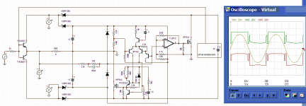
Those sims are looking good.
Efficiency can be calculated from:
SUM(ABS(AVG(losses ))) / SUM(ABS(AVG(loss + power output)))
I used Pspice not Tina, so i dont know how easy it is on that.
FOR THOSE INTERESTED HERE IS THE DOWNLOAD LINK FOR MY RESEARCH:
------------------------------------------------------------------------------------
Finlinson_Craig_MSc_Thesis.pdf - download now for free. File sharing. Software file sharing. Free file hosting. File upload. FileFactory.com
------------------------------------------------------------------------------------
Hope it works!!
Cheers
Craig
Not a lot of interest now it seems, maybe this thread would have attracted more attention in the Class-D forum?
It's a 50-50 mix of linear and Class-D so it was a tough one as to where to post!
Ontoaba, did that method of efficiency calculation work for you? what kind of efficiencies are you getting with your system? You'll need to run the simulation over a few cycles to get a steady average efficiency, if Tina is slow maybe LTSPICE is faster??
You will be able to lower the THD many times using NFB, the output impedance of the linear amplifier is important here, but at the same time so is the bandwidth!
A large concern for maintaining efficiency is the nominal impedance of the load, low impedances will cause efficiency to drop off at lower signal bandwidths (reduced power bandwidth).
In my report I investigated envelope tracking aswell (including the Carver magnetic field amplifier!), this might also be of interest, although I dont think it is as good a scheme as the parallel connection.
Cheers
Craig
Hi, Thanks your link is work.
I have problem with how to use tina-ti multimeter it always show zero AC voltage, may be I should make some sensor with low pass filters, and waiting its steady state(one cycle is very long for this circuits). I am not going to do that, your thesis is already show some efficiencies results that help in prediction.
Series connection has more lost power in its ripple which dissipated at linear stages. Carver using three tiers, may be he has some problem with fast rising current demand or something. Combining them like EEEngine (yamaha) and classBD (labgruppen) also help, but not much, I am using interleaved switches that help each other both in current rising and ripple reduction, but it become more complex. Mackie subwoofer using single tracking rail for both +/- supply that may help me in this.
🙂There is no perfect things in this temporary world, but we may try some improvement. Series connection has less efficiency and this parallel connection has higher ripple to be reduced, need twice voltage rating for devices and need better error correction. ClassD also has very low efficiency in low power operation, when heated inductors and its switcing losses dominated.
Low efficiency at low impedance load also caused by inductor limited dI/dt, lower the inductor value or use higher chargeing voltage will solve it. Or simply use interleaved as in my early post with two switches, it handle up to 2 ohm for 8ohm design.
Attachments
Last edited:
The problem with low impedance loads is a tricky one to get rid of, if you raise the supply voltage of the class D stage then you also raise its dissipation, and increase the switching frequency. Lowering the inductor will also cause the oscillation frequency to rise. Efficient Power bandwidth is reduced at lower Z loads.
I guess the frequency of oscillation needs to be capped / better controlled to stop it rising too much in this scheme.
I’m not familiar with EEEngine and classBD, do you have a good link for each?
P.S. by interleaved do you mean correction currents centred about 0V?
P.P.S do you intend to build one of these amplifiers? That would be really interesting if so 🙂, unfortunately I don’t have much time to myself right now so I cant try any practical experiments.
It would be very interesting to hear the sound produced, as the scheme undoubtably can be made to work very well in THD measurements (TIMD may be another matter!).
Cheers
Craig
I am agree with that, higher frequency will lower the efficiency, but lowering the inductors will result in faster current capability and frequency could be controlled at lower range.
This is quoted from eeengine thread, about eeengine and classBD
It is up to you to built one or study them more before realize one, If you don't have enough time, simulation is very useful.
This is quoted from eeengine thread, about eeengine and classBD
The Labgruppen FP3400 schematics you can download form here
Categorized Schematics and Service Manuals for free download I-N
And I attached Yamaha T3n power amp with EEEngine
And maybe this has something to to with this Yamaha patent
Amplification circuit
It is up to you to built one or study them more before realize one, If you don't have enough time, simulation is very useful.
Hi Craig,
Sorry I didn't spot your thread earlier! You might be interested in this paper I presented at the most recent Audio Engineering Society convention:
AES E-Library: Switching/Linear Hybrid Audio Power Amplifiers for Domestic Applications, Part 1: The Class-B•D Amplifier
This paper is going to be peer-reviewed soon for publication in their journal and as such I have been told that I must not distribute it (but you can still buy it from the AES), sorry about that.
You might also be interested in my PhD thesis on High-Efficiency High-Fidelity Audio Power Amplification which you can get here.
I'm currently very busy designing inverters for driving piezo-electric actuators, supervising undergraduate projects and a bit of lecturing, but I am still interested in hybrid audio amplifiers and intend to continue my research and will be working on a series linear/switching hybrid next. IHMO, these offer more promise than the parallel approach, but it may be that neither is really worth the effort 🙂() given how good pure class-D is becoming.
- Status
- Not open for further replies.
- Home
- Amplifiers
- Solid State
- The Composite / Hybrid- Linear + Switching Power Amplifier