Thanks Joel
Your power supply circuit is quite interesting. I was wondering ...
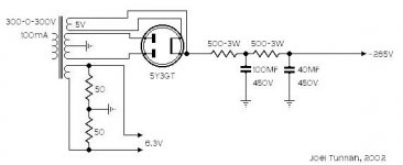
a choke is not needed? Would there be an advantage of having a choke and a RC network?
Its another newbee question..
Thanks
Joe
Your power supply circuit is quite interesting. I was wondering ...
a choke is not needed? Would there be an advantage of having a choke and a RC network?
Its another newbee question..
Thanks
Joe
burnedfingers said:
This is because the average current of a class A stage is constant.
However, as soon as you start getting any asymetry, the current varies.
As a matter of fact you can check exactly how much 2nd harmonic distortion a class A stage has, by measuring the change in consumed current.
So, the answer to the question is: It depende how loud you want to play it.
If you want to get the max out; go for a lower impedance choke smoothed circuit.
If you want to economise, and don't want it loud. Use resistors.
Cheers,
The power supply, as it stands, is perfectly adequate as long as it doesn't run into distortion.I was wondering ...a choke is not needed?
This is because the average current of a class A stage is constant.
However, as soon as you start getting any asymetry, the current varies.
As a matter of fact you can check exactly how much 2nd harmonic distortion a class A stage has, by measuring the change in consumed current.
So, the answer to the question is: It depende how loud you want to play it.
If you want to get the max out; go for a lower impedance choke smoothed circuit.
If you want to economise, and don't want it loud. Use resistors.
Cheers,
Exactly what John said.
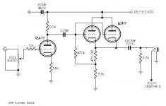
But you'll find that, whether used as a linestage, or to drive headphones - you will never need to push the tubes in this. There is plenty of gain, and a low enough output impedance to handle either task. A choke will only add cost... to this project. (I really do love chokes people! I swear. But you just don't need one all the time)
But you'll find that, whether used as a linestage, or to drive headphones - you will never need to push the tubes in this. There is plenty of gain, and a low enough output impedance to handle either task. A choke will only add cost... to this project. (I really do love chokes people! I swear. But you just don't need one all the time)
No, you probably don't need a choke there. But you might want to bypass that last filter cap with a film cap of a uF or so. A scope or some headphones and a cap will tell you if that's effective.
I didn't read the other discussion- why use a 6SN7 in the first place for this application? It's a great high voltage driver that can source some current, but for a CF intended to pass a couple of volts at most, a higher gm tube with higher mu might be a better choice from the standpoints of source impedance and distortion. Don't misunderstand me, a 6SN7 will work OK, it's just not optimal.
I didn't read the other discussion- why use a 6SN7 in the first place for this application? It's a great high voltage driver that can source some current, but for a CF intended to pass a couple of volts at most, a higher gm tube with higher mu might be a better choice from the standpoints of source impedance and distortion. Don't misunderstand me, a 6SN7 will work OK, it's just not optimal.
MU
Hi,
I agree higher gm is what makes a CF sing.
Even wouldn't mind a penthode there.
Personally IMO,it's tricky to implement.
You often get the effect"Who stole the bass?" when bypassing.
Cheers, 😉
Hi,
I agree higher gm is what makes a CF sing.
Even wouldn't mind a penthode there.
But you might want to bypass that last filter cap with a film cap of a uF or so. A scope or some headphones and a cap will tell you if that's effective.
Personally IMO,it's tricky to implement.
You often get the effect"Who stole the bass?" when bypassing.
Cheers, 😉
Well, if there's low frequencies moving around on the rail, you'll be able to spot it with the scope/phones. Though I don't see any reason why this should be greater with a bypass in place; the main effect of a bypass cap is seen at frequencies where the elytic is starting to get inductive.
I agree that a pentode would work well as the CF. For triode purists, a high gm triode (or a pair paralleled as Joel is doing with the 6SN7) will do nearly as well, but one generally has to accept 7 or 9 pin envelopes.
I agree that a pentode would work well as the CF. For triode purists, a high gm triode (or a pair paralleled as Joel is doing with the 6SN7) will do nearly as well, but one generally has to accept 7 or 9 pin envelopes.
Agreed. Though electrolytics can introduce distortion. They are a long way away from an ideal capacitor - BTW no voodoo here.the main effect of a bypass cap is seen at frequencies where the elytic is starting to get inductive.
IMO it is essential to have a large enough resovoir; that probably means it's going to be a bit inductive - so bypass it. But in doing do remember; youve made a parallel tuned circuit at "some" frequency. Best to avoid 'lytics if you're a puritan.
Best buy some shares in a PIO company.😉
Cheers,
SY said:I didn't read the other discussion- why use a 6SN7 in the first place for this application?
Because I have a shoebox full of them.

do you use both halves of the 12AY7 ?
Ie 1 half for left channel 1 half for right ?
and the 5Y3GT is connected to the 300+- on the xformer right ?
Ie 1 half for left channel 1 half for right ?
and the 5Y3GT is connected to the 300+- on the xformer right ?
WHILE ASLEEP.
Hi,
Hoping good ole'Joel doesn't mind me answering your Q.:
I think he uses 1/2 12AY7 per chanel and B+ would be 285Vdc.
Correct me if I'm wrong.
Cheers,😉
Hi,
Hoping good ole'Joel doesn't mind me answering your Q.:
I think he uses 1/2 12AY7 per chanel and B+ would be 285Vdc.
Correct me if I'm wrong.
Cheers,😉
It took me a while to find out that the tubes were dual. I happened to run across a site that I could download the specs of the tubes. Couldn't you just use 1/2 of the 12AY7 tube?
Also, the 6SN7 design is kind of a textbook example of a push pull circuit does anyone have anything kinda new and exciting?
Joe
Also, the 6SN7 design is kind of a textbook example of a push pull circuit does anyone have anything kinda new and exciting?
Joe
Isn't the circuit without the 12aY7 a push pull? Isn't this a classic 40's 0r 50's design? The circuit I'm pointing to is the 6SN7 circuit.
It may be my old eyes, but it sure looks like a plain vanilla cathode follower, made from two paralleled sections of a 6SN7. I'm completely missing the push-pull part. Enlighten me, please?
I think Joe's referring to the SRPP circuit posted by frank?
Anyway, if you're referring to the one in this thread Joe, this is NOT push pull. It is single ended.
And, there is nothing "new" in any recent tube design! It's all been done before... in one form or another. But that doesn't make it any less fun.🙄
Anyway, if you're referring to the one in this thread Joe, this is NOT push pull. It is single ended.
And, there is nothing "new" in any recent tube design! It's all been done before... in one form or another. But that doesn't make it any less fun.🙄
Your eyes are OK Sy. It's a parallel CF.
Burnedfingers, I think you need to take another look at the circuit.
Later
Bruce
Burnedfingers, I think you need to take another look at the circuit.
Later
Bruce
Sorry about that!
Question....
I have some 5R4's and was wondering if I could use one in place of a 5Y3 in Joel's power supply circuit. I think it has a 5volt heater but then I don't own any tube manuals. What changes would I have to make in order to use the 5R4?
Thanks
Joe
Question....
I have some 5R4's and was wondering if I could use one in place of a 5Y3 in Joel's power supply circuit. I think it has a 5volt heater but then I don't own any tube manuals. What changes would I have to make in order to use the 5R4?
Thanks
Joe
- Home
- Amplifiers
- Tubes / Valves
- The complete 6SN7 preamp