Hi,
I started this thread to share experiences regarding stepped horns. Basically
any horn may be stepped, FLH, BL, TH, TL, TQWP etc. The point is to
approximate the continuous cross section area expansion or reduction with a
several steps of contant width to ease manufacturing.
Please feel free to post your experiences, theories, simulations and builds or
links to it.
Here is a good example and some theory at the end
http://www.diyaudio.com/forums/subwoofers/210339-tapped-horn-th-121-build.html
From page 5:
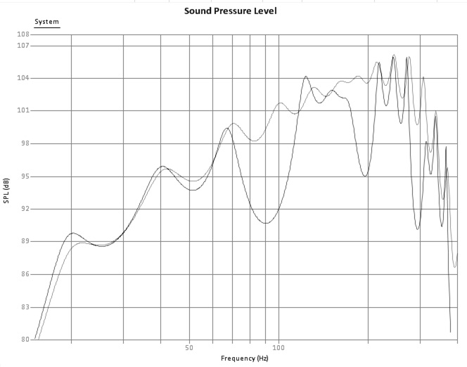
Here is a simulation of a exponential front loaded horn using B&C 15TBW100
in a 520 cm long 160-2000 cm2 horn with the driver 20 cm offset from the
throat. 3200 cm2, 34,2 cm long closed rear chamber, 109,44 dm3.
1-6 segments of equidistant lengths have been compared to the
pure exponential horn. Note that the accuracy increases with the number
of segments.

Black curve: 1 segment
Gray curve: pure exponenial
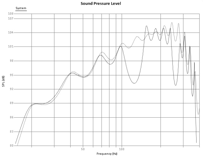
Black curve: 2 segment
Gray curve: pure exponenial
Black curve: 3 segment
Gray curve: pure exponenial
Black curve: 4 segment
Gray curve: pure exponenial
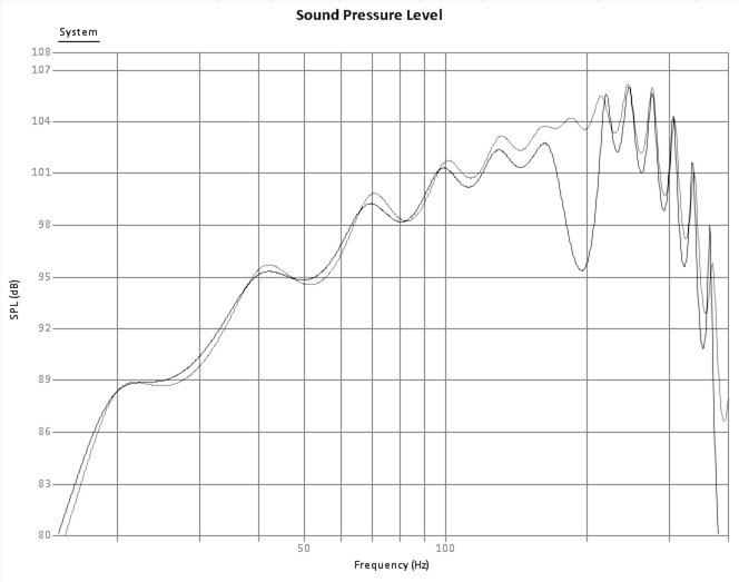
Black curve: 5 segment
Gray curve: pure exponenial

Black curve: 6 segment
Gray curve: pure exponenial
/Petter
I started this thread to share experiences regarding stepped horns. Basically
any horn may be stepped, FLH, BL, TH, TL, TQWP etc. The point is to
approximate the continuous cross section area expansion or reduction with a
several steps of contant width to ease manufacturing.
Please feel free to post your experiences, theories, simulations and builds or
links to it.
Here is a good example and some theory at the end
http://www.diyaudio.com/forums/subwoofers/210339-tapped-horn-th-121-build.html
From page 5:
Here is a simulation of a exponential front loaded horn using B&C 15TBW100
in a 520 cm long 160-2000 cm2 horn with the driver 20 cm offset from the
throat. 3200 cm2, 34,2 cm long closed rear chamber, 109,44 dm3.
1-6 segments of equidistant lengths have been compared to the
pure exponential horn. Note that the accuracy increases with the number
of segments.
Black curve: 1 segment
Gray curve: pure exponenial
Black curve: 2 segment
Gray curve: pure exponenial
Black curve: 3 segment
Gray curve: pure exponenial
Black curve: 4 segment
Gray curve: pure exponenial
Black curve: 5 segment
Gray curve: pure exponenial
Black curve: 6 segment
Gray curve: pure exponenial
/Petter
Last edited:
Good work, remarkable correlation on this one. In your 6 step example a lot of the passband doesn't match up but it isn't off by more than about 1 db anywhere until it gets past a 3 octave passband. Even the 4 step example is remarkably close for more than 2 octaves.
Here's my 6 step example from the linked thread.
My results were not nearly as good as yours. 1/4 wave rule says my 100 cm steps should provide good correlation up to 86.25 hz. i've got a 1 db difference at the low knee and a 2 db difference up at 86.25 hz.
Your previous 5 step example also had the same issues.

The longest segment was 66.3 cm so the 1.4 wave rule says correlation should be good up to 130 hz but you have a 1 db difference at the low knee (and a clearly visible frequency shift at the low knee as well) and a 1 db difference at 130 hz (for a wide frequency range). The 5 step example in post 1 has a much better correlation this this one. These two previous examples from the other thread show that you don't really know what you are going to get when following the 1/4 wave rule. You might get a good correlation like the new example here in post 1 or you might get something else like these previous examples.
In the example in post 1 the longest segment is 86.7 cm in the 6 step example so the 1/4 wave rule says there should be good correlation up to 99.5 hz. And in this example the correlation is remarkable all the way up to 160 hz for a full 3 octave passband with only 1 db of difference mostly at the top of the passband and a low knee that overlays almost perfectly (with only a small divergence above the low knee).
I think the lesson here is that if you are ok with your sim being off by a up to a couple of db at various points in the passband (both at the low knee and higher in frequency) then the 1/4 wave rule is "close enough". if you want more accurate results you should sim a stepped design as a stepped design. The software used here is simple enough to use and a sim only takes a couple of minutes. Even when following the 1/4 wave rule the results are close but not the same, in some cases (like my example in particular) having quite obvious differences across the entire passband.
Here's my 6 step example from the linked thread.
An externally hosted image should be here but it was not working when we last tested it.
An externally hosted image should be here but it was not working when we last tested it.
My results were not nearly as good as yours. 1/4 wave rule says my 100 cm steps should provide good correlation up to 86.25 hz. i've got a 1 db difference at the low knee and a 2 db difference up at 86.25 hz.
Your previous 5 step example also had the same issues.
The longest segment was 66.3 cm so the 1.4 wave rule says correlation should be good up to 130 hz but you have a 1 db difference at the low knee (and a clearly visible frequency shift at the low knee as well) and a 1 db difference at 130 hz (for a wide frequency range). The 5 step example in post 1 has a much better correlation this this one. These two previous examples from the other thread show that you don't really know what you are going to get when following the 1/4 wave rule. You might get a good correlation like the new example here in post 1 or you might get something else like these previous examples.
In the example in post 1 the longest segment is 86.7 cm in the 6 step example so the 1/4 wave rule says there should be good correlation up to 99.5 hz. And in this example the correlation is remarkable all the way up to 160 hz for a full 3 octave passband with only 1 db of difference mostly at the top of the passband and a low knee that overlays almost perfectly (with only a small divergence above the low knee).
I think the lesson here is that if you are ok with your sim being off by a up to a couple of db at various points in the passband (both at the low knee and higher in frequency) then the 1/4 wave rule is "close enough". if you want more accurate results you should sim a stepped design as a stepped design. The software used here is simple enough to use and a sim only takes a couple of minutes. Even when following the 1/4 wave rule the results are close but not the same, in some cases (like my example in particular) having quite obvious differences across the entire passband.
Last edited:
Hi,
I started this thread to share experiences regarding stepped horns. Basically
any horn may be stepped, FLH, BL, TH, TL, TQWP etc. The point is to
approximate the continuous cross section area expansion or reduction with a
several steps of contant width to ease manufacturing.
Nice work. Hey, you see that leftmost "notch" in the FR that moves up as you move to shorter and shorter segment lengths? I think that's happening at the corresponding 1/2W for the lengths in question. Perhaps this is why TD suggested a 1/2W rule instead of a 1/4W rule.
Thanks for your comment Just a guy and Brian I also reacted to the similarity of
the example is post 1. Compared to my comparison in your post, the main
difference as I see it is that all segments have equal length in post 1. Even
though the expansion differ, the relative expansion between each segment
of my simulation in your post should find its equal in post 1. I would also like
to add a comment about the expansio rate.
afd = 'Area seg n + 1' / 'Area seg n'
Segments: 2, area difference factor: 3,5
Segments: 3, area difference factor: 2,3
Segments: 4, area difference factor: 1,9
Segments: 5, area difference factor: 1,7
Segments: 6, area difference factor: 1,5
Since mainly all horns are compromises regarding mouth size, I think it is of
higher interest to discuss maximum difference in area difference between
each segment rather than the length of the specific segment. This way,
your simulation would much more accurate. Please make a recalculation for
your own. especially your last segment has a very high flare compared to
the previous.
To sum up my thoughts, if all segments are of equal length and the adf is
constant (preferably lower than 1,9-1,7), then you're safe. If the segment
lengts differ, this may affect the freq. response more than predicted than if
they all were of equal length. You'll better do a simulation to be sure.
There are a few reasons to investigate the stepped vs non stepped flare concept. These are off the top of my head, there may be more.
1. To prove or disprove Danley's claim that a stepped flare provides exactly the same results as non stepped (context will be provided later).
2. To be able to simulate a non stepped flare but build it stepped (this requires point #1 to be true).
3. To be able to take an existing design and convert it to stepped (this also requires that point #1 has to be true).
In the next few posts I'll introduce some discussion points on these points as well as the area difference factor and requirements for equal length stepped segments as brought up in post 4.
Last edited:
1. To prove or disprove Danley's claim that a stepped flare is exactly the same as non stepped.
Here's is Danley's exact quote -
So far we've looked at 3 different examples, two provided by Petter and one posted by me. The results are a mixed bag ranging from very similar in the example in post 1 to quite different in both the other examples. Because of the two examples that do not show good correlation I think it's a mistake to take Danley's quote literally, it's either simply not always true or it needs some qualifiers at least.
Petter brings up two possible explanations for the differences in the two examples that do not correlate well = area difference factor and segment lengths that are not equal. I would like to investigate this further.
Here's is Danley's exact quote -
Imagine a horn, that was 6 meters long, with a 28 Hz flare and a 7 sq. meter
mouth area. Instead of making a traditional horn, one made it out of pipes of
stepped diameters, a "digital" horn. How many steps do you have to have before
it works like a horn, any guesses?.
Well if one made each pipe 1 meter long and did the expansion in 6 steps what
would you get? You get the exact same thing as a true exponential horn up to
150 Hz. What you see in the radiation resistance is a small wiggling around
compared to the expo BUT with the right driver, that does not show up in the
acoustic output. The effect of the steps does put a pretty deep notch in the
response but the 1 meter step's first notch is at 200 Hz and the next at 400
Hz and so on. Using this box below 150 Hz, there is essentially no difference
between the two.
So far we've looked at 3 different examples, two provided by Petter and one posted by me. The results are a mixed bag ranging from very similar in the example in post 1 to quite different in both the other examples. Because of the two examples that do not show good correlation I think it's a mistake to take Danley's quote literally, it's either simply not always true or it needs some qualifiers at least.
Petter brings up two possible explanations for the differences in the two examples that do not correlate well = area difference factor and segment lengths that are not equal. I would like to investigate this further.
First as a baseline I recreated Petter's 6 step example in post #1 exactly to see if I got the same results. I did not, but this could be simply due to different t/s parameters entered. I used the t/s provided here - B&C Speakers
I input the numbers exactly from the chart in post 1 for the 6 step example including the driver offset and I got these results.
The most troubling part to me is that the low knee doesn't overlay like it does in post 1. Regardless the correlation is not that bad.
I tried Petter's Excel method to overlay them but it doesn't work for me. I have Excel 2003 and it doesn't work the way Petter describes which is too bad because overlaying would be a much better view.
I input the numbers exactly from the chart in post 1 for the 6 step example including the driver offset and I got these results.
An externally hosted image should be here but it was not working when we last tested it.
The most troubling part to me is that the low knee doesn't overlay like it does in post 1. Regardless the correlation is not that bad.
I tried Petter's Excel method to overlay them but it doesn't work for me. I have Excel 2003 and it doesn't work the way Petter describes which is too bad because overlaying would be a much better view.
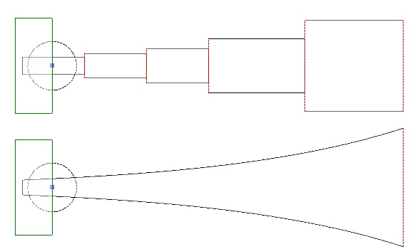
Moving on, I took Petter's example horn and chopped it into 6 segments of various differing length as follows.
In line two of each segment you can see the cross sectional areas for the expanding flare segment as well as the area difference factor.
In line 3 is the cross sectional area for the corresponding stepped segment.
Line 4 is the segment length which is the same for both expanding and stepped.
Line 5 is the segment volume which is the same for both expanding and stepped.
segment 1
160 - 260.1 (1.6 adf)
206 stepped
100
20.6
segment 2
260.1 - 331.5 (1.3 adf)
294 stepped
50
14.7
segment 3
331.5 - 538.9 (1.6 adf)
427 stepped
100
42.7
segment 4
538.9 - 875.8 (1.6 adf)
694 stepped
100
69.4
segment 5
875.8 - 1116.5 (1.3 adf)
992 stepped
50
49.6
segment 6
1116.5 - 2000 (1.8 adf)
1516 stepped
120 (71.9 hz)
181.9
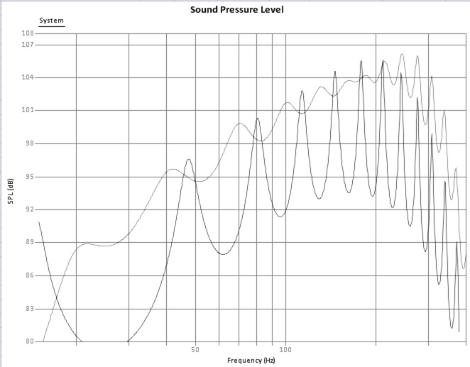
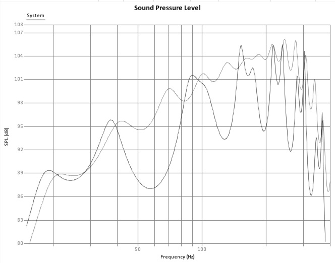
The first line shows the original flare schematic and frequency response.
The second line shows the original flare chopped into 6 segments (note frequency response is slightly different, not sure why - note that the overall flare is exactly the same volume).
The third line is the stepped equivalent to the chopped 6 segment horn.

The 100 cm steps have adf = 1.6 and the longest 120 cm step has adf = 1.8. This is within Petter's adf limit but even so, the correlation here is not good.
So what is causing this? Is it the adf or the different step lengths or something else?
The 1/4 wave rule says correlation should be good up to about 72 hz and it kind of is ok up to 72 hz but there is the notable difference at the low knee.
I don't think different segment lengths alone cause a problem. For example, if we used 40 segments and they were all different lengths but acoustically very small I think the correlation would be very good.
So the problem may be that there are just too many segments that are too long, in other words what Petter calls adf.
In line two of each segment you can see the cross sectional areas for the expanding flare segment as well as the area difference factor.
In line 3 is the cross sectional area for the corresponding stepped segment.
Line 4 is the segment length which is the same for both expanding and stepped.
Line 5 is the segment volume which is the same for both expanding and stepped.
segment 1
160 - 260.1 (1.6 adf)
206 stepped
100
20.6
segment 2
260.1 - 331.5 (1.3 adf)
294 stepped
50
14.7
segment 3
331.5 - 538.9 (1.6 adf)
427 stepped
100
42.7
segment 4
538.9 - 875.8 (1.6 adf)
694 stepped
100
69.4
segment 5
875.8 - 1116.5 (1.3 adf)
992 stepped
50
49.6
segment 6
1116.5 - 2000 (1.8 adf)
1516 stepped
120 (71.9 hz)
181.9
The first line shows the original flare schematic and frequency response.
The second line shows the original flare chopped into 6 segments (note frequency response is slightly different, not sure why - note that the overall flare is exactly the same volume).
The third line is the stepped equivalent to the chopped 6 segment horn.
The 100 cm steps have adf = 1.6 and the longest 120 cm step has adf = 1.8. This is within Petter's adf limit but even so, the correlation here is not good.
So what is causing this? Is it the adf or the different step lengths or something else?
The 1/4 wave rule says correlation should be good up to about 72 hz and it kind of is ok up to 72 hz but there is the notable difference at the low knee.
I don't think different segment lengths alone cause a problem. For example, if we used 40 segments and they were all different lengths but acoustically very small I think the correlation would be very good.
So the problem may be that there are just too many segments that are too long, in other words what Petter calls adf.
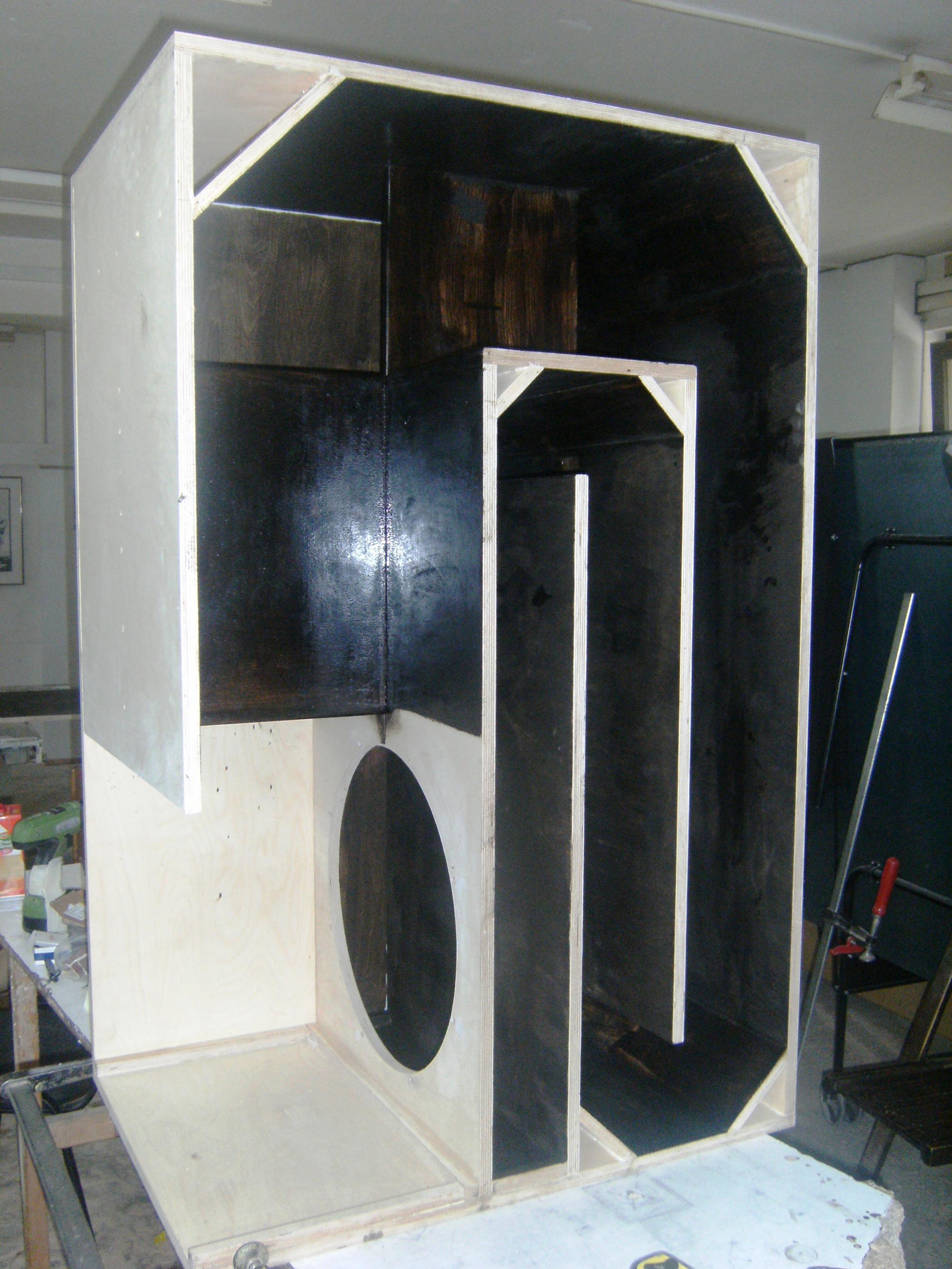
If different segment lengths did cause a problem even if adf was low, this is a problem in itself. It's very hard to make a horn with equal all equal length segments. As Brian shows with his POC2 it is possible if the line is a constant cross sectional area - The Subwoofer DIY Page v1.1 - Projects : A "Proof of Concept" tapped pipe - Construction
But when the segment cross sectional areas are all different it can start to become a bit of a nightmare to fold. it would be VERY difficult to fold a 6 step tapped horn with all equal length segments. Front loaded horn would be a bit easier but would probably end up with a non rectangular box since the rear chamber is usually fairly small in volume and needs to be deep enough to fit the driver.
If you get really creative there might be a more elegant way to do this but the requirement to have all equal length segments makes the folding part a lot harder.
If all the steps need to be equal length to get an accurate sim, and if having all equal length segments makes the design incredibly difficult to fold, then what's the point of being able to easily sim a stepped design as non stepped?
As I mentioned in the last post I don't think that the equal segment length is a requirement as long as you use a lot of step and keep them all quite small, but if it is a requirement as Petter states then it causes a big issue for folding.
But when the segment cross sectional areas are all different it can start to become a bit of a nightmare to fold. it would be VERY difficult to fold a 6 step tapped horn with all equal length segments. Front loaded horn would be a bit easier but would probably end up with a non rectangular box since the rear chamber is usually fairly small in volume and needs to be deep enough to fit the driver.
An externally hosted image should be here but it was not working when we last tested it.
If you get really creative there might be a more elegant way to do this but the requirement to have all equal length segments makes the folding part a lot harder.
If all the steps need to be equal length to get an accurate sim, and if having all equal length segments makes the design incredibly difficult to fold, then what's the point of being able to easily sim a stepped design as non stepped?
As I mentioned in the last post I don't think that the equal segment length is a requirement as long as you use a lot of step and keep them all quite small, but if it is a requirement as Petter states then it causes a big issue for folding.
Now let's look at designs with naturally high adf.
Exponential T (or M if you prefer) = 1. This isn't a really popular flare. A lot of bass horns use a lower T, and that means they are much more flared than pure exponential, which means a naturally higher adf at the end of the line than at the beginning. Contrast that to pure exponential T=1 where the flare rate is constant throughout the entire path length, which means adf at the beginning of the line = adf at the end of the line and at all other points.
There's a lot of popular bass horns that have a rapidly increasing flare towards the end of the line. Let's look at the folded Labhorn.
The area at the mouth (green line) is about 913.5 sq inches. The area 5 inches back from the mouth (orange line) is about 735 sq inches. That's a huge expansion in only 5 inches and for that 5 inch segment alone adf = 1.24.
The area at the red line is about 399 sq inches, and that's about 30 inches back from the mouth. So the adf between the red line and the green line = 2.28. 30 inches is about 1/4 of the length of this horn and the last 30 inch segment has very high adf so an expanding flare sim won't match a 4 step stepped model at all.
So how many step would we need to keep the last segment adf reasonably low? The area at the purple line is about 507.6 sq inches, so the adf of the segment between the purple line and the mouth (green line) = 1.8, which is at the high end of acceptable adf as described by Petter. This segment area from purple line to green line is about 15 inches. The Labhorn is about 126 inches long and if the last segment has to be 15 inches max to get a good correlation between flared and non flared sim, we need 8.4 (round up to 9 or down to 8, whichever you like) steps.
So for horns that flare more than pure exponential (T=1) you need more steps to keep adf low.
Exponential T (or M if you prefer) = 1. This isn't a really popular flare. A lot of bass horns use a lower T, and that means they are much more flared than pure exponential, which means a naturally higher adf at the end of the line than at the beginning. Contrast that to pure exponential T=1 where the flare rate is constant throughout the entire path length, which means adf at the beginning of the line = adf at the end of the line and at all other points.
There's a lot of popular bass horns that have a rapidly increasing flare towards the end of the line. Let's look at the folded Labhorn.
An externally hosted image should be here but it was not working when we last tested it.
The area at the mouth (green line) is about 913.5 sq inches. The area 5 inches back from the mouth (orange line) is about 735 sq inches. That's a huge expansion in only 5 inches and for that 5 inch segment alone adf = 1.24.
The area at the red line is about 399 sq inches, and that's about 30 inches back from the mouth. So the adf between the red line and the green line = 2.28. 30 inches is about 1/4 of the length of this horn and the last 30 inch segment has very high adf so an expanding flare sim won't match a 4 step stepped model at all.
So how many step would we need to keep the last segment adf reasonably low? The area at the purple line is about 507.6 sq inches, so the adf of the segment between the purple line and the mouth (green line) = 1.8, which is at the high end of acceptable adf as described by Petter. This segment area from purple line to green line is about 15 inches. The Labhorn is about 126 inches long and if the last segment has to be 15 inches max to get a good correlation between flared and non flared sim, we need 8.4 (round up to 9 or down to 8, whichever you like) steps.
So for horns that flare more than pure exponential (T=1) you need more steps to keep adf low.
Last edited:
I would like to do another comparison with a 0.5 T hyp/ex horn (like the Labhorn original design before folding) but I don't know how to calculate the segment volumes when it's cut into pieces. The software used here can't help with that, if you split the segments of a hyp/ex horn the flare rate and overall volume changes.
If anyone knows how to calculate the volume of segments of a hyp/ex horn let me know. The pure exponential T=1 comparisons here are interesting but most horns are not T=1.
I'd also like to do a more conical shaped flare like most tapped horns and very low tuned bass horns have as I think they will end up pretty accurate as the flares don't flare that much, but that's for another day.
If anyone knows how to calculate the volume of segments of a hyp/ex horn let me know.
Just to clarify - do you want to be able to calculate the volume of segments having an actual hypex expansion profile, or do you want to be able to calculate the volume of segments having either a conical or a parabolic profile, but connected in series to approximate an overall hypex horn?
Just to clarify - do you want to be able to calculate the volume of segments having an actual hypex expansion profile?
Yes, I want to take a 0.5 T hyp/ex horn, chop it into 6 segments and calculate the volume of each segment. At no point will I be converting anything to CON or PAR until that is done.
Even if I wanted to convert the hyp/ex horn to CON or PAR expanding segments, the only way I can think of to do that accurately is to export the horn flare dimension data from Hornresp, enter it into Excel, graph the flare and then draw straight segment lines on it to match the curve as closely as possible. I suppose I could do that but I think it might be easier and more accurate to just skip that completely and calculate the volume of the actual hyp/ex segments.
Thanks for your work Just a guy, I'll be gone som days and will reflect later. Can't you integrate it to get the volume? That 's what I did in the exponentiell case.
Last edited:
I don't know what you mean by "integrate it".
If you use the software to split the horn the flare changes dramatically both in shape and volume. I think what's happening is it's creating two 0.5 T flares instead of just cutting the existing flare in half, which is a very different thing.
It's interesting to note that splitting a pure exponential horn also changes the frequency response a bit, which should not happen. The change is subtle but watch the frequency response as you make the first split in an exponential horn and the frequency response changes. After you split it a bunch of times it's more similar to the un-split horn but this is interesting and I'm not sure what's happening because the total volume of the flare does not change at all.
Yes, I want to take a 0.5 T hyp/ex horn, chop it into 6 segments and calculate the volume of each segment.
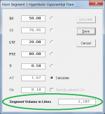
Why not just use the Hornresp Horn Segment Wizard to find the required volumes?
In the attachment, S1 is the area at the throat of a segment, L12 is the length of the segment, F12 is the horn flare cutoff frequency and T is the horn flare parameter (0.5 in your case).
Attachments
I don't know what you mean by "integrate it".
I suspect that it means to use integral calculus to derive the formula for the volume. Hornresp has already done that for you 🙂.
It's interesting to note that splitting a pure exponential horn also changes the frequency response a bit, which should not happen. The change is subtle but watch the frequency response as you make the first split in an exponential horn and the frequency response changes.
I can't speak for other simulation programs, but if you are using Hornresp, and if Cir > 1 for the complete horn, then an isophase wavefront model is used. For the multiple segment equivalent, a plane wavefront model is used. This is why you may see a slight difference in the results.
If Cir <= 1 for the complete horn then a plane wavefront model is used, and the results will be identical to those for the multiple segment (plane wavefront) equivalent.
I think what's happening is it's creating two 0.5 T flares instead of just cutting the existing flare in half, which is a very different thing.
Why is it different, if the original T is also 0.5?
The Horn Segment Wizard results would suggest otherwise 🙂.
Why not just use the Hornresp Horn Segment Wizard to find the required volumes?
In the attachment, S1 is the area at the throat of a segment, L12 is the length of the segment, F12 is the horn flare cutoff frequency and T is the horn flare parameter (0.5 in your case).
Why is it different, if the original T is also 0.5?
The Horn Segment Wizard results would suggest otherwise 🙂.
Hornresp does the same thing that TL.app does when splitting the hyp/ex horn into segments. The individual segments do not add up to equal the original hyp/ex flare.
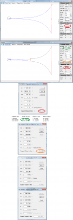
This is really difficult to explain so I'll attempt to do it in a way that can be followed along with pics.
First I'll start with a really big hypex horn with T=0.5. I'll use 100 for S1 and 10000 for S2 and 500 for L12 so we can use even numbers and get some dramatic results.
In image 1 you can see that TL.app calculates the volume of that flare to be exactly 976.1445 liters, circled in red. Now let's skip down to image 3 and Hornresp calculates the exact same volume for this flare, circled in red.
NOW we split the horn up and start getting into some real trouble. In image 2 I told TL.app to split the horn in half. Note that the flare total volume (both segment 1 and segment 2 added together) has changed, circled in red. It went from 976.1445 liters to 904.08011 liters. The only thing that changed was that I split it in half. Now I have two flares, each with T=0.5 and they do not add up to the same volume as the original unsplit T=0.5 flare. Everything else is the same, throat area, mouth area and length.
Also note that in image 2 the cross sectional area at the split is 786.56 circled in green and the first segment volume is 76.803238, circled in orange.
Now let's begin the split procedure in Hornresp. Image 4 (in text) shows the Horn Data for the original unsplit flare. (One segment, S1=100, S2=10000, L12=500). I only need to know the volume at the exact midpoint, so I used 250 cm segment lengths. The cross sectional area at the midpoint is reported by Hornresp Horn Data as 786.560736 sq cm, circled in green. Now look back at image 2, the area at the end of the first segment (the midpoint) is 786.56, circled in green. So both TL.app and Hornresp agree that the cross sectional area at the midpoint of the flare should be 786.56.
Unfortunately that's where the similarities to the original flare end. Let's continue the split procedure in Hornresp. Referring now to image 4 (right after the text Horn Data) I've specified the inputs for the first flare, S1=100, S2=786.56, L12=250 and T=0.5. Hornresp reports the volume for that segment as 76.803 liters, circled in orange. Look at image 2 again, circled in orange the first segment is 76.803238. So both Hornresp and TL.app agree on the volume of the first segment, but this is not correct compared to the original unsplit flare.
(This is not shown anywhere in the images but TL.app says the volume of the second segment in image 2 is 827.27687. Hornresp specifies the volume of a S1=786.56, S2=10000, L12=250 and T-0.5 segment as 827.277 liters. So again, TL.app and Hornresp agree that the second segment is the same volume, but again this is not correct compared to the original unsplit flare.)
If we take the two split segment volumes (Hornresp and TL.app both agree that they are 76.803 and 827.277 liters respectively), we end up with 904.08. Now look back at image 2, circled in red the total SPLIT flare volume is 904.08.
The volume of the SPLIT flare (904.08) is NOT the same as the volume of the original UNSPLIT flare (976.145). Not in TL.app and not in Hornresp.
As I said before the reason is because two back to back T=0.5 flares do not equal a single T=0.5 flare, and I'm pretty sure that is correct. EACH T=0.5 flare is increasing hyperbolic towards the end of the segment, so two back to back flares start out somewhat hyperbolic at the beginning of the first flare, then get more and more hyperbolic approaching the end of the first segment, then at the start of the second segment we are again at just somewhat hyperbolic and getting increasingly more hyperbolic towards the end of the second flare. Imagine two LeCleach flares back to back, they would not equal a single LeCleach flare in the same way that two back to back 0.5 T flares do not equal a single 0.5 T flare. This LeCleach example is easier to visual because at the end of each segment the LeCleach flare begins to flare so much that it folds backwards so if you put two LeCleach flares back to back it would not equal a single LeCleach flare.
Now let's try this another way, instead of letting Hornresp calculate F12 like I just did, we'll let it calculate AT like you did in the attachment picture.
In this case we need to specify F12, so let's go back to the original unsplit flare in image 3. Hornresp calculates the original flare as 28.34. So referring to images 6 and 7, I've input the start areas of the two segments, the length, the flare T=0.5 and F12=28.34. Clearly this is even more wrong than the previous method, as in both cases the calculated mouth area AND segment volume is too low.
So clearly we would have to use different F12 and/or different flare T for the two segments to equal a single 0.5 T flare. But at this point it's getting beyond me and I could fool around with different F12 and different flare T until the volumes match up but if I can't prove they are mathematically the same as a single 0.5 T flare then it probably won't be.
if you are not able to blow this picture up enough to read clearly the original link is here. Image - TinyPic - Free Image Hosting, Photo Sharing & Video Hosting
If you still can't blow it up enough with that link to see it clearly I'll host it somewhere else, let me know.
EDIT - I attached the pic to the bottom of the post as an attachment as well, that should allow it to be blown up to full size so it should be legible.
An externally hosted image should be here but it was not working when we last tested it.
Attachments
Last edited:
- Status
- Not open for further replies.
- Home
- Loudspeakers
- Subwoofers
- The collaborative stepped horn project