@caglarm
Can you post your SPICE file?
I have tested with my SPICE.
2x24VAC Transformer 10.4 Watt at THD 0.100%
With 2x25VAC Transformer 11.4 Watt.
2x28VAC Transformer 14.8 Watt at THD 0.100%
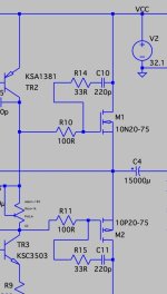
2x24VAC 32.1VDC 900mA Out:10.4W Heatsink:2x29W
2x25VAC 33.5VDC 930mA Out:11.4W Heatsink:2x31W
2x28VAC 37.7VDC 1.050A Out:14.8W Heatsink:2x39W
Can you post your SPICE file?
I have tested with my SPICE.
2x24VAC Transformer 10.4 Watt at THD 0.100%
With 2x25VAC Transformer 11.4 Watt.
2x28VAC Transformer 14.8 Watt at THD 0.100%
2x24VAC 32.1VDC 900mA Out:10.4W Heatsink:2x29W
2x25VAC 33.5VDC 930mA Out:11.4W Heatsink:2x31W
2x28VAC 37.7VDC 1.050A Out:14.8W Heatsink:2x39W
Sure..
(35v for clean 10.0W no clip) input 1.152vP
(35v for clean 10.0W no clip) input 1.152vP
Attachments
Last edited:
Just tried a layout . I am learning PCB layout so there may be some errors

I use MultiSim.
Thanks for your files and PCB.
Unfortunately I can not use ms14 files.
I run Multisim 12.
Thanks for your files and PCB.
Unfortunately I can not use ms14 files.
I run Multisim 12.
It is a mystery.Sure..
(35v for clean 10.0W no clip) input 1.152vP
Why do you get different results from my results.
At 32.1V I get 10.4W
The ouput voltage should be adjusted to VCC/2+0.45 Volt.
For VCC=32.1V this gives 16.50V at output node.
For VCC=32.1V this gives 16.50V at output node.
i mean is there a sonic benefit using bipolar and maybe foil in parallel?No.
C5 15000uF is one electrolytic with +/- poles.
Attachments
BTW... for input frequency 20kHz I get oscillation in the simulation. I fear that might also be true in real life. I found this way to put snubbers on the FTEs in some thread I do not remember.
That prevents that oscillation.
@xrk971 has PCBs for this on which you can mount the MOSFETS closely to the snubber elements.
Mo
That prevents that oscillation.
@xrk971 has PCBs for this on which you can mount the MOSFETS closely to the snubber elements.
Mo
Attachments
Last edited:
Well, I have consider this as two other have found the same.
10 Watt seems to be optimistic.
The only way is to increase Voltage supply.
Maybe use 2x25VAC transformer which should give like 33.5VDC.
This should give at least 9 Watt output.
Remember when you test using 32.1V, that the output node should be at 16.50V. Not at 50% of the supply voltage.
About the oscillation you have found.
Maybe increase the compensation cap?
Funny I get 10.4 Watt output and have not seen any oscillation.
I have run using oscilloscope function with squarewave 20 kHz and more.
Last edited:
I do not know if this is just an LTSpice awkwardness. It happens only if I use rather small simulation steps (like 1/freq/1000) and not always.
Found the snubber boards for the MOSFETs again: https://www.diyaudio.com/community/threads/alpha-nirvana-39w-8ohm-class-a-amp.344540/post-5966619
Test board is ready, it's good enough for testing the design, and by request it's not crowded.

I'm sure there will be more modifications on the schematic, so final one will be of better layout and standardised to some common heatsink/case. Will be rechecking schematic and pcb tomorrow before posting gerber, i'm tired like a dog atm, don't want a mistake to creep on.
I'm sure there will be more modifications on the schematic, so final one will be of better layout and standardised to some common heatsink/case. Will be rechecking schematic and pcb tomorrow before posting gerber, i'm tired like a dog atm, don't want a mistake to creep on.
- Home
- Amplifiers
- Solid State
- The BULLET Amplifier 10 Watt Class A and Current FB