Here you are.@lineup , Can you give me your multisim simulation file? I want to see if there is a difference between the versions.
I hope you can load .ms12 files.
I can not use .ms14 files.
Attachments
Yes, it does a little. But not too much.I indeed had adjusted the output voltage to VCC/2. Changing to 12.5V does not do too much. The distortion starts at 0.2W more.
33.5V with 2x25VAC transformer and VCC/2+0.45 gives 17.20V output.
Try 33.5V, please
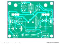
Now we wait for Gerber files.Test board is ready, it's good enough for testing the design, and by request it's not crowded.
View attachment 1215715
I'm sure there will be more modifications on the schematic, so final one will be of better layout and standardised to some common heatsink/case. Will be rechecking schematic and pcb tomorrow before posting gerber, i'm tired like a dog atm, don't want a mistake to creep on.
You are so nice to make this for me 🙂

@lineup ; Yes, your simulation data is correct. but the data is not pure classA.
For pure classA, I expect the bias current to be the same as the peak currents. As you increase the bias current, distortion increases. This problem disappears when you increase the supply voltage.


For pure classA, I expect the bias current to be the same as the peak currents. As you increase the bias current, distortion increases. This problem disappears when you increase the supply voltage.
The bias current is 0.9A.@lineup ; Yes, your simulation data is correct. but the data is not pure classA.
For pure classA, I expect the bias current to be the same as the peak currents. As you increase the bias current, distortion increases. This problem disappears when you increase the supply voltage.
For push-pull this means 1.8A output peak.
1.8A x 8 Ohm = 14.4Vpeak
This is well more than 12.65Vp which is the 10 Watt level.
I begin to wonder if you two have the same SPICE MODEL for the ECX10N20 and ECX10P20.With 33.5V 10W still is a bit over, I think. With 35V, I get 10W with only 0.0026% THD. In the waveform of the Id's it can be seen that it is not clean anymore, but not to the degree of causing much distortion, it seems.
VCC 35V, input 1.2V. Current in lower FET.
So here are the models I use:
Attachments
n
No you do not need source resistors at all for lateral mosfets, only if you want to put some in parallel. Nor is thermal feedback necessary.You need source resistors for power transistors and some kind of thermal feedback to stabilize the quiescent current thru power transistors, at least if you want a stable and reliable system over time.
I've rechecked schematic, and pcb, no drc errors, so here's gerber. As usual this is test pcb, it may not work (small chance (many spice tests here) but i gotta say it). Dimensions are 100x80mm, 2$ on jlcpcb so cheap for test. If it passes without oscillations, or any other issue, and additional new modifications, there will be v1 release. Enjoy.
Attachments
mkk76
The 2N5551's collector output should be connected to KSA1381's base. As per your scheme, you have drawn the KSA1381 base connected to the DC offset resistor string. as a result the amp will not work. Similarly your PCB has the same mistake.
The 2N5551's collector output should be connected to KSA1381's base. As per your scheme, you have drawn the KSA1381 base connected to the DC offset resistor string. as a result the amp will not work. Similarly your PCB has the same mistake.
Regarding the SPICE models, I suspect that there are two different models. The first is probably based on the old Hitachi 2SJ50/2SK135 where there was a significant Rds resulting in a loss of available voltage swing across the mosfet, hence less power output. The second is probably a revised model where there is less Rds to reflect the current Exicon mosfet hence more power is produced. I believe Exicon have been refining their production of the lateral mosfets over time. In my experience given the same voltage and current conditions, the Exicon mosfets produce slightly more power that the older Hitachi mosfets. I also suspect that someone decide they were identical thus copied the Hitachi model and relabelled it Exicon.
I used this type of amp in a car stereo 125w rms
Into 4 ohms using LF353 as a zero offset bias.
Irf530 and 9530 sounded fantastic from 1991 to 2017 .
Into 4 ohms using LF353 as a zero offset bias.
Irf530 and 9530 sounded fantastic from 1991 to 2017 .
@ Brijac, a few comments on your gerber file as shown in post #72.
The 8 ohm resistor you show at the output is not required - that is actually the speaker coil.
Also, you show component values on the silk screen, but should also show the component number - eg R1, C1 etc to avoid confusion.
Just my 2c worth.
The 8 ohm resistor you show at the output is not required - that is actually the speaker coil.
Also, you show component values on the silk screen, but should also show the component number - eg R1, C1 etc to avoid confusion.
Just my 2c worth.
The question is what models are the most correct.No, I do not. Mine was included in above LTSpice file. They are different.
Will try what happens when using yours.
EDIT: LTSpice crashes when I try to use yours.
I have compared my models with the datasheet for ECX10N20 and ECX10P20.
What I can see my models are a bit optimistic.
I think the truth is somewhere between my models and yours.
Here is a picture of PCB.mkk76
The 2N5551's collector output should be connected to KSA1381's base. As per your scheme, you have drawn the KSA1381 base connected to the DC offset resistor string. as a result the amp will not work. Similarly your PCB has the same mistake.
There is no need for heatsinks on the KSC3503 and KSA1381
Can we spot more errors?
Attachments
Last edited:
- Home
- Amplifiers
- Solid State
- The BULLET Amplifier 10 Watt Class A and Current FB