Introduction:
For years I've owned a Logitech X-503 multimedia system that provides the sound for my main PC. At the time I purchased it, it was around US$70, which was quite a good price, considering that the system consisted of 10" small 1.7" drivers (two in each of the satellites) and a 4" driver in a gnat-sized vented box to provide bass duties. The satellites aren't too bad (nothing that can't be fixed with a bit of EQ), but the bass unit was definitely a study in compromises. The driver has a relatively high Q and the box is tuned to around 80 Hz, so the end result is a big peak around that frequency that makes everything sound "robust", until you notice that a lot of the low notes are actually missing. Interestingly enough, the output from the bass unit's amplifier is not rolled off (significantly) below 80 Hz, which means that the driver does end up getting signal below Fb. The amplifier must incorporate some sort of dynamic EQ though, because even when turned up, there's no sounds of significant distress from the driver when it's fed very low frequencies.
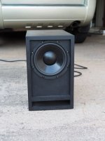
Anyway, with no very low frequencies to speak off, the "bass unit' had to go, and I decided to replace it with a subwoofer design based around the Dayton DCS205 8" subwoofer driver. For this particular design, I wanted a solution that had an Fb around 32 Hz, as my intent was to use EQ to address the low-frequency performance in-room, and the lowest band on the simple EQ included with the PC was centered at 32 Hz.
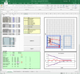
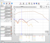
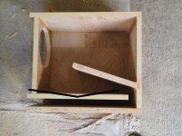
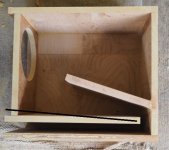
So, I went to work on a new Excel workbook to describe the design, and I eventually came up with an MLTL-looking design that was around 26.6 litres net and 45 litres gross, primarily due to the use of 21mm MDF for the build. The corresponding Hornresp sim showed a response that gently slopes down from 100 Hz to just above 30 Hz, just right for what I wanted. The workbook is also able to export a data file in the required format for easy importing into Hornresp, which made the whole simulation process a lot easer. Note that in Hornresp I opted to include in the model the effect of puttling some polyester fiberfill in the first section of the alignment. According to the sim, this would drop the resonance frequency (Fb) a bit, and smooth the response in the passband. Real-world measurements of the built subwoofer confirm that the added filling achieved these goals. Note also that the predicted frequency response in Hornresp is slightly optimistic, as Hornresp does not account for the impact of box losses. The rolloff from 100 Hz to 40 Hz is slightly steeper than predicted, and the "corner" at around 32 Hz is a bit shallower.
Results
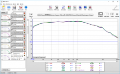
After building the box, the first thing I did was perform an impedance measurement, which suggested that Fb, which turned out to be around 33 Hz, was pretty close to that predicted by the Hornresp simularion I also performed some linearity tests, to see if subwoofer maintained its frequency response at higher input power levels (which would happen if port compression was low). Hornresp predicted that Xmax would start to be exceeded at 24.3V (the equivalent of just under 150W), and I tested at up to 25.4V (the equivalent of just over 160W). The subwoofer maintained its composure up to about -6dB, and then vent noise started to become audible. Still, it reached around -3dB from the peak input, or basically 80W, before the response at lower frequencies changed noticeably (according to the measured response), As this subwoofer is not going to see anything more than 25W in actual use (it's going to be powered by the Logitech X530's amplifier, after all), it looks like I'm never going to hear that vent noise - a good thing because this subwoofer is going to be located about three feet away from me, right behind my desk. Peak THD is also pretty low at 5.22% at about 20W input, most of which is 2nd order, so a lot less noticeable and objectionable. This suggests that the subwoofer is going to sound "clean" in actual use, and I can confirm that it does.
Conclusion
After messing around with tapped horns for awhile, it was nice to return to a relatively simple alignment, and this little subwoofer based around an 8" driver delivers all that I need for my multimedia system. If I was building this for another purpose, I might likely opt to flare the port's exit a bit, to reduce vent noise and compression effects at high volumes even further.
For years I've owned a Logitech X-503 multimedia system that provides the sound for my main PC. At the time I purchased it, it was around US$70, which was quite a good price, considering that the system consisted of 10" small 1.7" drivers (two in each of the satellites) and a 4" driver in a gnat-sized vented box to provide bass duties. The satellites aren't too bad (nothing that can't be fixed with a bit of EQ), but the bass unit was definitely a study in compromises. The driver has a relatively high Q and the box is tuned to around 80 Hz, so the end result is a big peak around that frequency that makes everything sound "robust", until you notice that a lot of the low notes are actually missing. Interestingly enough, the output from the bass unit's amplifier is not rolled off (significantly) below 80 Hz, which means that the driver does end up getting signal below Fb. The amplifier must incorporate some sort of dynamic EQ though, because even when turned up, there's no sounds of significant distress from the driver when it's fed very low frequencies.
Anyway, with no very low frequencies to speak off, the "bass unit' had to go, and I decided to replace it with a subwoofer design based around the Dayton DCS205 8" subwoofer driver. For this particular design, I wanted a solution that had an Fb around 32 Hz, as my intent was to use EQ to address the low-frequency performance in-room, and the lowest band on the simple EQ included with the PC was centered at 32 Hz.
So, I went to work on a new Excel workbook to describe the design, and I eventually came up with an MLTL-looking design that was around 26.6 litres net and 45 litres gross, primarily due to the use of 21mm MDF for the build. The corresponding Hornresp sim showed a response that gently slopes down from 100 Hz to just above 30 Hz, just right for what I wanted. The workbook is also able to export a data file in the required format for easy importing into Hornresp, which made the whole simulation process a lot easer. Note that in Hornresp I opted to include in the model the effect of puttling some polyester fiberfill in the first section of the alignment. According to the sim, this would drop the resonance frequency (Fb) a bit, and smooth the response in the passband. Real-world measurements of the built subwoofer confirm that the added filling achieved these goals. Note also that the predicted frequency response in Hornresp is slightly optimistic, as Hornresp does not account for the impact of box losses. The rolloff from 100 Hz to 40 Hz is slightly steeper than predicted, and the "corner" at around 32 Hz is a bit shallower.
Results
After building the box, the first thing I did was perform an impedance measurement, which suggested that Fb, which turned out to be around 33 Hz, was pretty close to that predicted by the Hornresp simularion I also performed some linearity tests, to see if subwoofer maintained its frequency response at higher input power levels (which would happen if port compression was low). Hornresp predicted that Xmax would start to be exceeded at 24.3V (the equivalent of just under 150W), and I tested at up to 25.4V (the equivalent of just over 160W). The subwoofer maintained its composure up to about -6dB, and then vent noise started to become audible. Still, it reached around -3dB from the peak input, or basically 80W, before the response at lower frequencies changed noticeably (according to the measured response), As this subwoofer is not going to see anything more than 25W in actual use (it's going to be powered by the Logitech X530's amplifier, after all), it looks like I'm never going to hear that vent noise - a good thing because this subwoofer is going to be located about three feet away from me, right behind my desk. Peak THD is also pretty low at 5.22% at about 20W input, most of which is 2nd order, so a lot less noticeable and objectionable. This suggests that the subwoofer is going to sound "clean" in actual use, and I can confirm that it does.
Conclusion
After messing around with tapped horns for awhile, it was nice to return to a relatively simple alignment, and this little subwoofer based around an 8" driver delivers all that I need for my multimedia system. If I was building this for another purpose, I might likely opt to flare the port's exit a bit, to reduce vent noise and compression effects at high volumes even further.
Attachments
Last edited:

MLTL Worksheet
Hi Brian,
I am trying to understand S2. Can you pl. show it on the sketch ? Is it possible to get the Worksheet that you have used ?
Thanks !
Jayant
Hi Brian,
I am trying to understand S2. Can you pl. show it on the sketch ? Is it possible to get the Worksheet that you have used ?
Thanks !
Jayant
I am trying to understand S2. Can you pl. show it on the sketch ? Is it possible to get the Worksheet that you have used ?
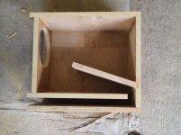
S2 is where the driver is located. As it's around a bend, some guesstimation is done in the spreadsheet to "derive" S2 when you tell it how far down the baffle the driver is located.
The spreadsheet is available in the thread that I use to cover all of those spreadsheets for describing folded horns - Spreadsheet for Folded Horn Layouts...
It's just a ported box, no?
Functionally, yes, just modeled as an MLTL. My intent here was to smooth out the 100Hz~200Hz region, which can (according to the sim) be affected by the location chosen for the driver on the baffle due to the size of the vent. I expect that the internal panel does load the vent a bit, but this is taken into consideration in the model.
Can i downscale this to be used in a dual TB W5-1138SM design ?
I don't see why not. You can adjust the box dimensions in the spreadsheet until you get something that's interesting, then export the results to Hornresp for analysis.
That woofer requires a looong port to work properly, passive radiators might be more practical.Can i downscale this to be used in a dual TB W5-1138SM design ?
Hmm.. I used the TB5 woofers in the tham6 and volvoreter30hz designs. They taking dust and want to build/test something with those little drivers combined in one design.
Nice work Brian!
So if I am following the topmost section provides the offset for the woofer down the line?
Did you experiment with the slope of the central divider?
Kind of a hybrid, no taper slot loading like a VB with the divider making it like a MLTL?
Did you experiment with some taper on the slot?
So if I am following the topmost section provides the offset for the woofer down the line?
Did you experiment with the slope of the central divider?
Kind of a hybrid, no taper slot loading like a VB with the divider making it like a MLTL?
Did you experiment with some taper on the slot?
Nice work Brian!
So if I am following the topmost section provides the offset for the woofer down the line?
Did you experiment with the slope of the central divider?
Kind of a hybrid, no taper slot loading like a VB with the divider making it like a MLTL?
Did you experiment with some taper on the slot?
Answers:
1.Yes.
2. No.
3. Yes.
4. No. It's not possible to have two internal 180 degree folds on one continuous taper and still keep the box rectangular.
I ask for two reasons, a better Anarchy box that is more like a normal slot loaded vented, and a way to build this with slot loading rather than the PR:
Digger8 Sub - diggity dig it all the way to 20Hz - Techtalk Speaker Building, Audio, Video Discussion Forum
With perhaps this woofer instead of the JBL, as I mentioned in the other thread:
Tang Band W8-740P 8" Subwoofer
Your design with the woofer you chose is more efficient and makes more sense with lower powered amps but I think something like your box with a plate amp is what I've had in
mind as a slot loaded version of that Digger8 with the higher output woofers.
The Anarchy TH is 2.9 cu ft external dimensions based on this:
LittleMike's Anarchy Tapped Horn - Home Theater Forum and Systems - HomeTheaterShack.com
and I think that a slot loaded Digger8 in 1.5 cu ft (the .5 for the slot) would crush
the Anarchy - probably with the TB woofer but would be less efficient.
Your design with the more efficient Dayton might be closer and I'd expect
with more output - need to compute VD for each driver.
Last edited:
Re #4 I was thinking of this in black, hope you don't mind using your pic:
No probs using the pic. Building the last section like that is possible yes, but Hornresp does not have enough segments to sim it. Now, if we shift the top internal panel so it's joined to the bottom one instead of to the back, this will shift S1 to just above the bottom internal panel and the result can be simmed by using an approximation for S1. What you will find though that the optimum place for S2 will no longer be on the driver baffle, but on the top panel.
Re #4, After drawing that and thinking about it more the upper shelf might be considered an internal flare which led to this:
This layout can be simmed in Hornresp, but it does complicate the build a bit, and the resonant frequency will go up for the same overall box volume. The optimization routine in my spreadsheet will no longer be applicable, of course.
If you want to flare the vent, it should be possible to do it and be able to sim the results in Hornresp AND continue to use the optimization routine in my workbook by using the flare I suggested on the web page I put together for that build. The workbook will have to be modified to accommodate the flare, of course, something I can have a look at in a few days if necessary.
- Home
- Loudspeakers
- Subwoofers
- The Boom Unit...