If you consider a low amplitude high frequency signal superimposed on low frequency large displacement amplitude there seems would be Doppler effects generating due to time shifting over the arc of the cantilever relative to the equivalent of an infinite length cutter arc. The magnitude of these errors appear subject to RPM. To be clear I can't comment on the significance, just that time shifting seems must exist.Thinking again, I realised that the shape if a waveform may become slightly distorted because of the differing movement between cutter and cantilever, but not the pitch.
And symmetric waveform distortion leads to uneven harmonics but not to IMD.
So all IMD must be generated by scuffing and speed variations in the record because of excentricity imperfections.
Hans
Yes, when you have two frequencies at the same time, you may get intermodulation products.
Don’t know whether the length of the cantilever plays any role in that.
Wow and flutter can be measured for instance with a simultaneous 300Hz and a 3Khz tone.
The generated IM products are caused here by the platter not running at constant speed over one revolution plus the contribution of the cart’s Fres.
Hans
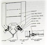
OK. But let's be clear, the cutter heads that cut 99.99% of all the records since the beginning of the stereo era don't move the cutting stylus tangentially. The arrangement in most cutter heads, in case you aren't familiar with it, is quite similar to the arrangement of the stylus and cantilever of the phono cartridge. There is a stylus at one end of a tube or rod, and a fixed pivot point at the other end which allows the stylus to swing in a complex motion as directed by the audio signal. That tube is called a cantilever in a phono cartridge, and it's called a torque tube in the cutter head, but it's conceptually the same.I was considering the arc of the cantilever as compared to a non-angle of a tangentially cutting cutter head. Tangentially cutting is equivalent to an infinite length stylus. In the case of a stationary record the contact point of cartridge with a short cantilever does not contact over the same contact points of the cutter moving tangentially across it. At the sides the short cantilever advances in time from its centre position. Alternatively if the sides are in real time a cantilever moving back to its centre is retarded in time. Don't know to whatever extent this is important but seems could be significant enough for consideration.
The cutter head itself is moved gradually across the surface tangentially of course. But that is just creating the spiral groove, it has nothing to do with the modulation of the groove.
The arc described by the playback stylus will be similar to the arc described by the cutting stylus but won't be identical because the cantilever is shorter than the torque tube. The torque tubes of Neumann and Westrex cutters are in the range of 10 mm in length. Cartridge cantilever lengths vary but they are all less than that.
The maximum distance traveled by the stylus from its center position while cutting the groove is about half a millimeter.
I understand what you are suggesting. My guess is that it won't be significant, but if you want to calculate it, at least you have some of the physical dimensions you would need.
For completeness we should acknowledge that there are a few cutter heads which don't use torque tubes, and to the best of my knowledge they do move the cutting stylus tangentially. They are the Ortofon and the JVC. If you have some records which were cut on these, and think this effect may be large enough for concern, you might prefer to play them back with one of the Decca cartridges which are built without cantilevers.
It seems to follow that spacial artifacts in a recording can't be realized in the absence of a signal(s). Hence signals present must be cleaner in some way in vinyl that permits the space to be realized, or alternatively that spatial cues can be somehow artificially enhanced by the nature of the vinyl playback system. It could be a combination of both.True. But I'm interested in probing remaining problems with digital. When it can reproduce a recording of a phono output with the space intact, then maybe some of other missing stuff will be found too. That is to say, I think don't its just the vinyl space that isn't getting reproduced properly.
In all the years of running stacked 57 ESL's the one recording that stood out the most in my system was the Cantate Domino by Harmonia Mundi.
Unfortunately you couldn't breath on the system without drastically upsetting the synergy, as I did by upsetting the setup of my Linn. In short "the music died".
IMO ESL's require pristine electronics to realize dynamics reaching into and coming out of the background. This is essential to obtaining dynamics to prevent becoming dull and/or lifeless. ESL's don't jump forward with dynamic punch like many high efficiency large surface paper cones. If one can deal with the radical peaks and valleys that many of the highest efficiency paper cones appear unblessed, they can rival or possibly surpass ESL's in the enjoyment IMO of having some experience. But not in inner resolution as far as I aware. The dynamic punch that dynamic speakers seem often to have is thought a function of real dynamics and a kind of faked "punch through" dynamic out of an obscured background. This often requires a more radical increase in SPL to obtain dynamics, being dependant for faked dynamic effect upon the amplitude of the background obscurity. Good dynamics often have extraordinary dynamics also at the lowest levels.
Last edited:
It is simply a thought experiment Bodyslam. I didn't know about the "torque tube" in cutter heads. Thanks. To further this thinking a little further. Are you aware if the torque tube is pivoted in line with the groove, or at a tangent to the groove. In order to neutralize(?) the affect requires a torque tube with equal length to the cartridge and with an axis along the groove line, being also pivoted on the same side as the cartridge. I don't really care about things I can't do anything about Bodyslam, just some general principles that might help in some DIY way. Yet thanks.
Last edited:
Here's some info on cutter head/torque tube/stylus support member. Possibly From Narma & Anderson, 1959(?) https://www.aes.org/publications/anthologies/downloads/jaes_disk-anthology-1.pdf


See also https://www.lathetrolls.com/viewtopic.php?t=796 for more from AES archives.
See also https://www.lathetrolls.com/viewtopic.php?t=796 for more from AES archives.
Attachments

Thx Dagfinn, great info especially your first AES link.
I will to try to get the full and lengthy document with all the backgrounds of storage technology.
Hans
I will to try to get the full and lengthy document with all the backgrounds of storage technology.
Hans
Yes Thx Dagfinn. Look at all those tubes!... how can all (please excuse the language) this **** work it looks so crude?
Expanding on thoughts of arcing of the stylus shank leaves me to think about a cutter head mimicking a 9" pivoted "standard" tonearm. In other words pivot the cutter head assembly at 9". This seems would fix up all those tracking angle errors. The hell with those tangential trackers and 12" tonearms.
Expanding on thoughts of arcing of the stylus shank leaves me to think about a cutter head mimicking a 9" pivoted "standard" tonearm. In other words pivot the cutter head assembly at 9". This seems would fix up all those tracking angle errors. The hell with those tangential trackers and 12" tonearms.
Hierfi,
Question is what it would bring in sound reproduction to have a pivoted cutter.
The biggest point against pivoting IMO is not the small tracking angle error but the skating forces pulling the cutter head to one of both groove walls depending on the anti skate force.
That’s also the advantage of a tangential tone arm, no skating forces.
But looking at Stereophiles recommended latest list, all arms are pivoted arms so all those potential errors aren’t as bad as it seems, but the pivot bearings and arm’s shape and material are obviously more important.
You can go as as high ad $100,000.- for a pivoted SAT arm, still without Cart and TT.
Hans
And there is the companion, covering the playback side of the game:
https://www.aes.org/publications/anthologies/downloads/jaes_disk-anthology-2.pdf
https://www.aes.org/publications/anthologies/downloads/jaes_disk-anthology-2.pdf
Good question Hans,Hierfi,
Question is what it would bring in sound reproduction to have a pivoted cutter.
The biggest point against pivoting IMO is not the small tracking angle error but the skating forces pulling the cutter head to one of both groove walls depending on the anti skate force.
That’s also the advantage of a tangential tone arm, no skating forces.
But looking at Stereophiles recommended latest list, all arms are pivoted arms so all those potential errors aren’t as bad as it seems, but the pivot bearings and arm’s shape and material are obviously more important.
You can go as as high ad $100,000.- for a pivoted SAT arm, still without Cart and TT.
Hans
I would need to sell off some stuff to afford the SAT... but to start you can only get so much for a rescue dog. I haven't heard the SAT arm. I have heard what I believe was the top of the line Kuzma. The system was revealing enough to make me think the arm was extraordinary. Didn't the SAT arm start out at something like $60,000? Michael Fremer loved it. I seem to recall that when it first came out the arm tube was of some kind of polymer or carbon fibre(?). I believe the new one has some form of rigid metal inner core. You would think they would have done it right the first time. An added $40K for what seems an afterthought fix?
I have experimented with the Ittok arm using electrical tape around and along the arm tube (it seems a better approach to start with a rigid metal core and then add controlled damping afterward). I also added a polymer (aka rubber) suspension to the base of the Ittok to the arm board. I cut about a 3" hole in the arm board and suspending the arm in the polymer which was then hung from the sides. I much preferred a triple point gapped arrangement as opposed to a continuous one. Interestingly, I also tried a thin flat flexing stabilizer bar going backward from a point at the base of the arm. This arrangement looked much like a cutter head implementation, only on a larger scale.
In what seems an affront to the natural order of things I experimented with tilting the turntable. The angle is set so the stylus moves up hill toward the centre as a substitute for conventional anti-skating. This also forces the spindle of the platter against the side of the bearing housing at the top and on the opposing side at the bottom, forming a more intimate pressure contact between the platter and the plinth than those sloppy bearings in old turntables of yesteryear (the bearings have been twice replaced by Linn over the years). Tightening tolerances is something high end turntables seem invariably to do now. Many also have a high mass sub chassis. This seems creating the greater authority that these possess. In any event it seems that tilting works well on the Thorens 125 which has a substantial sub chassis.
In what seems an affront to the natural order of things I experimented with tilting the turntable.

On TTs with suspended sub chassis, this can be achieved by adjusting the heights of the springs.
Skating forces is a pain. Antiskating schemes are not always the right pill.
Kogen has shown an in situ indicator , alas I have not built it
https://audio-creative.nl/wp-content/uploads/kogen_skatingforce.pdf
As a side bonus of tjhe tilt, on the belt driven models I am aware of, it happens that the motor pulley is in favor position for the side thrust due to belt tension over the spindle to be in opposition with the gravitational side force due to the tilting.
George
Anti-skating adjustments often seem sonically inconsequential, though I didn't realize the stylus wear was so severe in absence of it.
Just as a belt drive creates side thrust, idler wheel drives, like on the Thoren's TD124 and Lenco's, seem would produce more side thrust on the bearings than belts. A secondary factor is that idler drives provide a secondary mechanical path for stylus forces returning to the sub-chassis by the mechanism of their suspension.
It seems an often underestimated factor in turntable design is the gyro effect, causing spindle wobble when forces are applied off axis. Spindle wobble generates timing errors. The degree of wobble seems a function of the amount of force applied, the degree it is off axis, and the position and mass providing the opposing force. The higher the effective mass the less the gyro effect and timing errors. The effective mass can be considered made up of at least two mass bodies, a rotating and a stationary mass body. The degree to which they behave as one is dependant upon the transmissive integrity of the bearing(s) and other mechanics.
Side pressures takes up the slack in spindle bearings that increases the transmissive integrity supporting a higher effective mass, however this improvement can be offset by added excessive drag in the bearing. Although the tilting of the turntable may not be the answer, perhaps adding some form of idler wheel on the perimeter to provide greater transmissive integrity to the sub-chassis might. As an aside, the TD124 was redone by Thorens, though it seems wouldn't replicate the sonic character the original as the transmissive connectivity between the moving and stationary masses have been drastically altered.
You find me in agreement, the gyro effect included.
Only Lenco idlers, from the L78 and older had their idle wheel touching not the inner perimeter but the inner horizontal surface of the platter. It didn't cause side thrust but it could cause wobling, spindle bearing condition permitting.
George
Only Lenco idlers, from the L78 and older had their idle wheel touching not the inner perimeter but the inner horizontal surface of the platter. It didn't cause side thrust but it could cause wobling, spindle bearing condition permitting.
George
Attachments

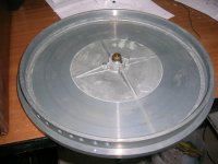
Nice photo's. There is a distinction between mechanical wobbling from poor mechanics and wobbling from a gyro effect.
A vertically contacting idler may be the best, as the horizontal contact can provide a vertical force upward in direct opposition to the downward force of the stylus. Having two points of contact between the moving mass and the stationary mass creates two moments around those contact points. Depending on the stylus contact in relation to the line between the contact points on the platter this can substantively reduce the gyro effect. There still remains a tipping moment where the contact of stylus isn't along the line between the pivotal points of the two platter supports.
A vertically contacting idler may be the best, as the horizontal contact can provide a vertical force upward in direct opposition to the downward force of the stylus. Having two points of contact between the moving mass and the stationary mass creates two moments around those contact points. Depending on the stylus contact in relation to the line between the contact points on the platter this can substantively reduce the gyro effect. There still remains a tipping moment where the contact of stylus isn't along the line between the pivotal points of the two platter supports.
This is a common feature of -6dB crossovers.I have made it very clear that these were 2-Way ho-hum speaker designs that are so boringly common and that they have a rising peak Z somewhere in the critical midrange.
Lately you have been mentioning the "isolation" this resistor may bring by way of inertia, hence the flywheel reference.Think of the massive amount of linear current drawn by 0.1R is like a flywheel. It is now that much more difficult for the driver to influence it.
Resistance has no such inertia.
Perhaps not.I am quite certain that what Isaac and others have heard is not delusional.
I have a Hitachi SR-303L which I was given along with a nice set of Pioneer fullrange speakers that I used in my garage for a time. This amp has a damping factor of 25 - https://www.radiomuseum.org/r/hitachi_lw_am_fm_stereo_receiver_sr_303l.html
I took the impedance plot of the Revel speaker that you have mentioned..
let us use Isaac's Revel M126Be speaker (the Z above) and not a single P17WJ-00-08 driver. Make the resistor 0.1R which is 80 times lower than nominal 8 Ohm of the speaker. Now the amplifier would hardly see the speaker at all,

Then I simulated it with my 320mΩ output impedance, with and without your 0.1Ω resistor in parallel (levels adjusted).
It's clear that the response has the potential to be affected enough that it could become audible. Certainly at the amounts suggested below, it would be.
- Home
- Member Areas
- The Lounge
- The Black Hole......