How do you connect mass with distortion here, mass is a linear property. Also, mass does not determine how good treble sounds.
I didn't.
Did you just post this on the wrong thread?
I thought this was against the rules?
It's from the Elsinore thread. Perhaps you could explain what was implied here..
Joe Rasmussen said:Hope a better tweeter can be incorporated...
Let me say something, and this is from a guy who makes arguably the best electrostatic speakers in the world by rebuilding Martin-Logan speakers with mylar that is 1/3rd the thickness than anybody is willing to try, and he says the tweeter as used in the Elsinore, with that waveguide and that crossover, has such low distortion that it matches the best electrostatics!
No kidding!
So no, I cannot see myself changing that tweeter for any other.
There are plenty of people who understand it and they now outnumber any who is here!
4: Publish in detail the measured test results for both versions when goal(s) achieved.
We have 630.000+ views of this thread. Are you unaware that nobody here made any post to support your explanation?4. NOT HERE!
Allen, what you have just done is crossed threads. This was explained in no uncertain terms was verboten, then why is it that you as a Moderator should do this?
This is not right. Are you following the rules or are you not? I have Jason's email, should I ask him?
You have dragged an event in a clean stream into a sewer!
Go back there and I will reply. And no, your argument is just plain wrong! I never said that!
This is not right. Are you following the rules or are you not? I have Jason's email, should I ask him?
You have dragged an event in a clean stream into a sewer!
Go back there and I will reply. And no, your argument is just plain wrong! I never said that!
Last edited:
Sorry to be late to the party, I had some spare time and read lots of posts here. I stumbled on this statement:
An impedance graph is a function of current, not voltage
... in the context of speaker drive. It's been a long time since I read such a testimony of total ignorance. Impedance, as was discovered already by Mr. Ohm, is the ratio of voltage to current, impedance = voltage / current.
Therefor, if you drive a speaker with current, necessarily the voltage across the speaker follows the impedance of the speaker to satisfy impedance = voltage / current.
With voltage drive, the current will follow the inverse of the impedance, again to satisfy current = voltage / impedance.
No amount of tap dancing and page-long posts will change that. This is basic electrical engineering 101.
Jan
Last edited:
This is not right. Are you following the rules or are you not?
Please read the rules and quote the one being broken...
On using a parallel eq network with current drive. When you do that, it is no longer current drive. That should be obvious, but let me explain nevertheless.
Current drive means you have a source that, whatever the load, delivers always the same current. It can be seen as a voltage source with an infinite output impedance. Load it with a speaker and whatever the speaker impedance, the current source forces the exact same current (within its capability) through the speaker.
Now add some network from the output of the current source to ground (lets call this the eq network). Now the exact same current goes through the network, because, it's a current source, right? Let's call this the compound current source.
Now load this compound source with a speaker, which places the speaker in parallel with the eq network. How much current is now going through the speaker? Well, it depends. The current source itself still delivers its current, but now some goes through the eq network, some goes through the speaker. How does that current divide through the eq network and the speaker? Well, that depends on their relative impedance. If both would have the same impedance, they would get each half of the current. The higher the speaker impedance, the lower the fraction of the total current going through it.
Electrical engineering tells us that we have replaced the original source which had infinite output impedance, by a source whose output impedance is the impedance of the eq network. Neither pure current nor pure voltage drive, something in between. As soon as you add anything in parallel to the current source, the resulting source no longer is a current source.
Jan
Last edited:
Thanks for the lesson... not.
1. Done. 2 Done. 3. Progress. 4. NOT HERE! 5. Not fully yet, but could be wider than first thought, remains to be seen.
What do you think I have been doing for the last fifty years, huh?
They should change the name of the thread to "School Yard, Home For Ignorant Bullies"?
Sorry, but when someone keeps moaning like a child, he will be treated like a child, it’s up to you.
As for me, I would appreciate when you could show us your 1. and 2. in a sober and technically responsible way.
But if you don’t want to show us the results I’m wondering again what your intentions are to post in a tecnical discussion thread, because 1. and 2. will not escape the level of brainstorming speculations.
Hans
"Yum, yum, me wants more"
Says the troll you just fed
Yes I agree, but at the same time I think that it's very important to put the nonsense presented questionable.
This thread has a lot of readers and some "or many" of them could be mislead to belive in the nonsense that is presented because he use an endless number of words and posts without saying anything at all exept that he knows everything and that everybody else are complete idiots that dont understand a ****.
Jan is a respected person and he is asking good reflected questions, so in my opinion he dont feed the troll, but simply ask relevant questions that its important to ask.
🙂
Stein
Well he's in the bin for a week. Now what were we talking about...
For a laugh Dan D'Agostino Master Audio Systems Progression M550 monoblock power amplifier Measurements | Stereophile.com. Not particularly impressive for $45000 a pair. I won't comment on how the reviewer didn't seem to notice significant cross-over distortion either...
For a laugh Dan D'Agostino Master Audio Systems Progression M550 monoblock power amplifier Measurements | Stereophile.com. Not particularly impressive for $45000 a pair. I won't comment on how the reviewer didn't seem to notice significant cross-over distortion either...
What I found embarrassing was the way SF defended the publication of a measurement of a broken amp with a call to 'transparency'.
Last time I looked, SF did not exist for the purpose of showing the transparency of its staff. SF exists to inform its readership.
If the staff f*cks up a measurement, the right thing to do is NOT to publish it and brag about transparency.
The right thing would be to NOT publish or retract the broken test, and redo it with a properly operating amplifier. That is service (remember that word?) to the readership.
I understand that JA is in the process to slowly extract himself from SF editorial management. Historically, that often signals a decline in quality. Hope they can avoid that in this case.
Jan
PS I have met JVS many years ago. He is a very nice guy, enjoyable company, but I would be hesitant to trust him with my solder iron.
Not sure what the transfer to Paul Miller will do though. I know he got rid of several staff, some for good reason some not really making sense. But at least he made his name measuring stuff.
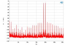
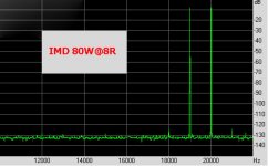
Well, not very impressive indeed when comparing those IMD figures to those measured with my 90% DIY Amp at a peak level of 80Watt@8R.
Noise is also not very impressive with 80.5dB from 22 to 22Kz ref 1W@8R
versus mine with -96dB up to 30Khz also ref 1W@8R.
For such an extremely expensive amp made by professionals, it seems disappointing to say the least.
Hans
.
Noise is also not very impressive with 80.5dB from 22 to 22Kz ref 1W@8R
versus mine with -96dB up to 30Khz also ref 1W@8R.
For such an extremely expensive amp made by professionals, it seems disappointing to say the least.
Hans
.
Attachments
....
As for me, they will be published on paper and PDF format. They will be peer-reviewed by a 'panel' that includes three physicists and several with trained with maths and engineering backgrounds - and they will be named on the paper....
I think you shall invite 1 or 2 of your worst/hardest opponents here to joint the review team. If you dare.
Proper reviewing holds a record of all written comments and a statement wether a comment in fact rendered a change or was ignored. This review record should be published along with the released, and by you approved, document marked with date and a proper revision number.
//
Hans what would your amp show at 1kHz with the 19+20?
Jan
Jan,
I searched, but to my regret I couldn't find the original files anymore to show the 1Khz IMD distortion that you asked for,.
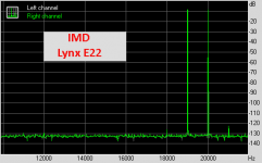
But what I can show you is the IMD of the used Lynx E22 Sound card in a loopback, already having practically the same peaks at 18Khz & 21Khz.
So in fact the measuring gear is here the limiting factor and the amp itself is probably even better as shown at this very IMD setting.
Hans
.
Attachments
@steve
I’m not a speaker guy (it’s black magic to me but I do wish speaker designers would keep impedance dips to no lower than 3 ohms) but the LF response seems to drop off quite early. Could you improve it by changing the LF resonance peak? Might of course mean a larger cab.
I think that working with a on purpose resonance is wrong to begin with - no? 🙂 Kind of DOA...
//
- Home
- Member Areas
- The Lounge
- The Black Hole......