I have an off-topic question regarding the cap value after a DC umbilical cord. First the spec’s:
Wire: 23 ga twisted pair, Teflon jacket
Length; 4 ft
DCR: .088 Ohms
Impedance: 122 Ohms
Capacitance: 48 pF
Inductance: 719 nH
My question is what value Capacitor do I use at the end of the umbilical? If I use the DC resistance for a low pass RC, the capacitance is very large for 15 Hz cutoff. Or what is a practical low pass cutoff – i..e. is 15 Hz impractical in this case? Is the filter only for high frequencies? 100kHz, 1 MHz?
Ahem... a capacitor at the end of the umbilical cord (whatever that is) to do what?
My bad. A capacitor the input of the regulator in the preamp box (where the umbilical cord feeds the preamp box with DC power from a separate PSU box) to filter anything picked up by the umbilical.
Last edited:
Nothing on hand, but do a search on "cycle by cycle control loop".
Is class D cycle by cycle or is it envelope control? (genuine question BTW)
Pics or it didn't happen. 😉
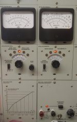
Radiometer CLT-1 component linearity Tester
10V across 20K Vishay S102 -170 dB HD3
Left meter is the 10KHz 10V (170 dB + 20 dB on the meter).
Right meter is the 30 KHz harmonic (1uV full scale) (20 dB + 0 dB meter reading)
190 dB - 20 dB = 170 dB. Which is the noise floor of the 30 KHz filter.
Attachments
Last edited:
Demian,
I read the test voltage as 30 ish volts and the harmonic as .1 uV ish which does give -170 dB ish results. Not bad. Looking at my results for a similar value, similar type, I measured -145 and dropping with frequency at 5,000 hertz for a 31,600 ohm Vishay. Extrapolating to 30,000 hertz I would expect -160 dB for the third harmonic! 25 volt test signal. Looking back at my notes, I thought most of the distortion was from my test amplifier limiting me to a best level of 170 dB and not the resistors under test absolute limit. Just might have to make a passive filter if I want to look even lower in the dirt.
I read the test voltage as 30 ish volts and the harmonic as .1 uV ish which does give -170 dB ish results. Not bad. Looking at my results for a similar value, similar type, I measured -145 and dropping with frequency at 5,000 hertz for a 31,600 ohm Vishay. Extrapolating to 30,000 hertz I would expect -160 dB for the third harmonic! 25 volt test signal. Looking back at my notes, I thought most of the distortion was from my test amplifier limiting me to a best level of 170 dB and not the resistors under test absolute limit. Just might have to make a passive filter if I want to look even lower in the dirt.
Last edited:
You probably do need a passive filter. The CLT-1 is a product of the late 1960's really. It started with Siemens as a way to find potentially defective parts. Its all passive LC filters and discrete amps.
I can switch ranges up to 25 V and see what happens. The instrument can deliver 1000V but the floor is not as low, and I'm not comfortable working around it on those ranges.
PM me if you want a copy of the manual.
I can switch ranges up to 25 V and see what happens. The instrument can deliver 1000V but the floor is not as low, and I'm not comfortable working around it on those ranges.
PM me if you want a copy of the manual.
When the IEC was updating the resistor test, they acknowledged my method but did not adopt it as they really didn’t understand it and thought it too complicated.
Thanks for the manual offer, but I have the original standard and the inductor data set. I actually have some inductors that are good enough and shielded. The funny shields that don’t have hysteresis.
I can go up to 150 VRMS. I noted you had the transformer module. Can’t imagine why a kilovolt on binding posts makes you nervous! 😉
Last edited:
"Can’t imagine why a kilovolt on binding posts makes you nervous!"
At least the binding posts have plastic insulation on them. My first amateur transmitter had +500V from a supply that could deliver 200 mA on uninsulated screw terminals on the back panel. If you were a dumba$$ and reached around while it was powered up you would join the heavenly choir in a hurry.
I passed that test at least...
Howie
Yes, but OTOH applying the linear theory to Class D has it's unique set of challenges. Like, for example, applying negative feedback to a system (an open loop class D amplifier) with a "dead zone" transfer function (in the time domain).
But if you take the output through a low pass, and feed that back to the input of the linear modulator, isn't that just (in concept) a linear control loop?
Jan
Class D cycle by cycle.
A class D amp with cycle by cycle control would be an amp that is using a loop to control the triangular or sawtooth wave, to make a perfect waveform and at the same time at the right time, it would be possible to design a low THD amp.
It could be used to design a Class D amp, but it's hard to put global feedback aroud it, it could run open loop, with all the downsides.
Last edited:
One cycle control of class-D amplifier:
https://pure.tue.nl/ws/portalfiles/portal/47020342/626934-1.pdf
US5617306A - One cycle control of bipolar switching power amplifiers
- Google Patents
https://pure.tue.nl/ws/portalfiles/portal/47020342/626934-1.pdf
US5617306A - One cycle control of bipolar switching power amplifiers
- Google Patents
A couple of things I recall from working with the power supply groups; one is that they had designed the "load-line" concept into their switching converters. This means the output drooped in a predictable way as a function of load current; in other words, it had an output impedance. Unsure if this concept has ever been used in a class D audio amp, but you could make the amp have a 1 Ohm output Z if you wanted. That might change how it behaves -sonically -when connected to a speaker.
If you look at most PC motherboards, you'll see they run multiple phases, which fire in staggered time. That reduces ripple and again, unsure if that concept has ever been used in a class D audio amp. That also might change how it behaves when connected to a speaker.
I realize such things are harder to do than what's going on now, but, whatever it takes to differentiate.
One cycle control of class-D amplifier:
https://pure.tue.nl/ws/portalfiles/portal/47020342/626934-1.pdf
US5617306A - One cycle control of bipolar switching power amplifiers
- Google Patents
Good catch
I haven't seen those before.
My answer was based on my own experience almost 20 years ago.
BTW: did they get the amp stable with global negative feedback?
I doubt that they did.
Last edited:
That's envelope control, I was talking about cycle by cycle control.
So you can get only 1 clock cycle error in the filtered output and any errors will be >> above the audio BW and easily filtered out. Similar to a Delta modulator in an A-D
In Praise of Instrumentation
I'd like to start a thread in praise of instrumentation!!
First: people are so impatient they do not use instrumentation to set up audio levels. I have seen this at radio stations, where DJs although they are trained to NOT just push a fader to "0", but to watch the levels as the music plays and adjust levels accordingly. Of course DJs are not trained audio engineers, but this also happens in studios to a lesser extent.
Second: I have now seen at multiple "high end" (major pop hitmakers) studios with producers and engineers of not that they run levels high enough so the channel VU meters hit the pegs, sometimes for seconds. When queried about that problem I was told: "ahh, it's not a problem, the console has 20 dB of headroom" to which I answered immediately: "And how can you know how much of that are you using if the meters are pegged?" What prompted me to look for issues was a clicking I could hear on bass guitar parts which sounded suspiciously like clipping to me, and sure 'nuff, once the levels were adjusted properly (lower channel input gain, raise buss feed level) the clicking disappeared. I consider this Audio Engineering 101 to know how to set up gain properly for all stages of the signal path to optimize both headroom and noise floor...
Thirdly and perhaps most importantly: Calibrated SPL meters should be employed far more frequently that they are. As most of us here know the inner ear has muscles that tighten to decrease sensitivity when confronted by loud sounds, a protective mechanism. What is less well known is the fact that this is not a binary mechanism. As SPLs increase these meat limiters begin to work, which not only lowers perceived levels, it modifies frequency response and perception of dynamics. I bring along my trusted General Radio 1585 Sound Level Measuring Set to every studio I participate in commissioning, both to verify standing waves and to monitor levels as we listen and tweak. Inevitably levels creep up and this needs to be pointed out as a factor changing perception, as Fletcher & Munson would agree. If one claims to have a keen ability to listen critically to sound systems for "accuracy" one aspect is most certainly the SPL and duration at that level. This is a deep and wide subject but at the core of our business and/or hobby.
I am recovering from a studio alignment today and will not be listening to anything, today...Silence is Golden.
Cheers,
Howie
- Home
- Member Areas
- The Lounge
- The Black Hole......