Complementary input stages have the problem of the compromise with using both types, both N and P together, BUT they can easily remove the need for an input coupling cap. THIS IS USEFUL!
For everyone else: All else being equal, PNP bipolars and Nch jfets are lower noise than their complements. This is due to the position of the N material in each device. N material has higher mobility than P material, and this lowers the resistance
John's exactly right ... but please don't forget there are two kinds of mobility, "bulk mobility" and "surface mobility". MOS transistors depend upon the latter, BJTs and JFETs depend upon the former.
And may God have mercy on your soul if you have to design with depletion mode MOS transistors. They can exhibit "buried channel" behavior and the effective mobility is a (bias dependent) weighted average of the bulk mobility and the surface mobility. Thank Buddha that CMOS is now mainstream and depletion MOS has fallen by the wayside. It was nasty.
For everyone else: All else being equal, PNP bipolars and Nch jfets are lower noise than their complements. This is due to the position of the N material in each device. N material has higher mobility than P material, and this lowers the resistance
Wow! Really, for everyone?
Horowitz and Hill 3rd edition provides plenty of measured data on pages 501 and 516: It is possible to choose PNP number X and NPN number Y, such that the chosen device Y has lower measured noise than the chosen device X.
Similarly H&H's data shows it is possible to choose PJFET number A and NJFET number B, such that device A has lower measured noise than device B.
The measured data backs up the "intuitively obvious" prediction. The maskset and the process are not insignificant. Not much of a surprise.
Similarly H&H's data shows it is possible to choose PJFET number A and NJFET number B, such that device A has lower measured noise than device B.
The measured data backs up the "intuitively obvious" prediction. The maskset and the process are not insignificant. Not much of a surprise.
Of course, all else being equal, which means similar masksets. Often P ch jets, for example, use a larger area maskset (I presume that is what you call it) compared to its N complement which equalizes its Gm, but then significantly increases its input C as well. This can create problems with high Z sources.
The new AudioExpress (AX-10-October-2020) has an article: "Ultra-Low distortion microphone buffer amplifier", crediting Scott W for a lot of the knowledge it conveys...
Good article putting some disparate sources in one context. Thanks again, Scott!
Howie
Good article putting some disparate sources in one context. Thanks again, Scott!
Howie
Who wrote it? I have a stash of the obsolete through hole FET's that I used, someone might find a few useful.
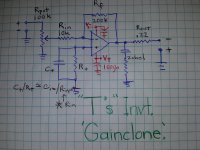
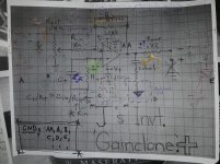
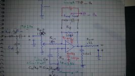
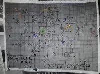
J's inverting gaincard integrated amp
😎
Go given that inductors are inherently hf blocking I just applied generic HF filt. to all inputs and outputs [except ps ...]
Also realized that thus there's way more that just the usual low level and PWR GND.
So it's a work in progress, ... er, ... will it explode?
.
.
.
...
.
.
.
No seriously ???11?1?® 😱
Cheers,
Jeff
...
But, just fer giggles, let's try this:
..puttin' the DIY BACK into diyaudio... 😉
Hun, so this is a recreation of " "T's" Inverted GainClone ". It obliviously 😉 wasn't his, but rather somebody took his idea of an inverted gainclone power amp and thru a pot on the front ...


...
...
A) You can choose the values on the +input so they match the -input's (better balance; tweak by actual measurement)
B) Invert. operation provides that nifty virtual ground that, because of the fet input, physically ACTS almost IDEAL [acting purely mathematical with no 'fudge'] and thus that has these tech. advantages ... blah, blah, blah, ... I can't recall what he said.
C) Well, because [in this particular case] the pot sets the input impedance, Rin and Rf can be dropped by an order of magnitude to provide better noise and more current through the resistors and junction that provides futher benifit by ... blah, blah, blah, I can't recall what I thought. ;}
D) So I'd like to correct and develop this circuit and build it and do some basic testing and listening and ... and, d o i t m y s e l f , ... if ya know what I mean ...
...
PS And YES that's how yer supposed to spell n e i g h b o U r s!!11!1!

😎
Go given that inductors are inherently hf blocking I just applied generic HF filt. to all inputs and outputs [except ps ...]
Also realized that thus there's way more that just the usual low level and PWR GND.
So it's a work in progress, ... er, ... will it explode?
.
.
.
...
.
.
.
No seriously ???11?1?® 😱
Cheers,
Jeff
Last edited:
You got that right (but the beer to truly celebrate being Canadian should be McAuslan's St-Ambroise Oatmeal Stout. ;-)
...
So it's a work in progress, ... er, ... will it explode?
Cheers,
Jeff
Jeff,
Thank you for the DIY Audio content, having used 3886's in an embedded application I can appreciate your studies...one question: what does paper Spice say about grounding? JK, I don't think any chipamp is quantified in a Spice model well enough to optimize ground paths. I did find normal single-point at the PS filter caps worked well. And IMHO, the output isolation network is not optional, at least the LM3886 does not like driving highly inductive loads, ask me how I know this (driving a motor...)
Have fun!
Howie
I wonder if it would be possible to communicate effectively JUST using a sequence of emoticons? Particularly conveyance of technical details... [wink-wink]
You could start a new thread with AudioLapDance and try to develop an innovative technical emoticon language.
Who knows, maybe our next amp build from a circuit diagram with emoticons could look like a real emoticon.
Hans
Who knows, maybe our next amp build from a circuit diagram with emoticons could look like a real emoticon.
Hans
I was going to say I've tried that, but no I used "emoji" and Unicode, the international standard character encoding that replaced ASCII. Emoticons are now an 'alternative' format, but will continue to exist because of the millions of forum posts using them.
https://twitter.com/ben__bradley/status/1151686349302485000
https://twitter.com/LIGO/status/1151670894114279426
https://twitter.com/ben__bradley/status/1151686349302485000
https://twitter.com/LIGO/status/1151670894114279426
I wonder if it would be possible to communicate effectively JUST using a sequence of emoticons? Particularly conveyance of technical details... [wink-wink]
...dude, that so american! 😉
that's what emoticons are for, AND how they're used in europe: just look at ALL the emoticons on yer fone. See the <--, -->, , clock, train, and poop emoji!

Most people only use what's on the 1st page, but there's pages and pages of them and they've been developed so that they can be used to convey fairly technical concepts ...
😉


.
.
.
.
.
.
I saw this after doing the above!
You could start a new thread with AudioLapDance and try to develop an innovative technical emoticon language.
Who knows, maybe our next amp build from a circuit diagram with emoticons could look like a real emoticon.
Hans
Seriously dudes, check out all the emoticons on yer fones, there's ....

Last edited:
Jeff,
Thank you for the DIY Audio content, having used 3886's in an embedded application I can appreciate your studies...one question: what does paper Spice say about grounding? JK, I don't think any chipamp is quantified in a Spice model well enough to optimize ground paths. I did find normal single-point at the PS filter caps worked well. And IMHO, the output isolation network is not optional, at least the LM3886 does not like driving highly inductive loads, ask me how I know this (driving a motor...)
Have fun!
Howie
...was she the one who submitted esoteric EE papers to little-known journals ...
😀
😎

...i'll keep an eye on that inductor...
Last edited:
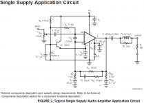
Extra components in single supply application ?!!?!?®
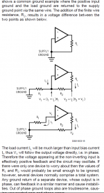
GND paths from 3886 datasheet
Reactive Loads from 3886 datasheet
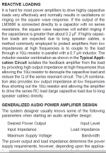
(only capacitive loads listed; so ... ?!?)
.
.
.
Extra components in single supply application ?!!?!?®
Since I have your ear,
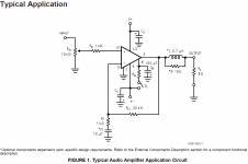
I've always wondered about the extra components in the single supple schematic [esp: Cc; and the stuff around/in feedback 'path' ].
What do you guys think of :
typical dual supply
single supply
component justifications
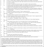


GND paths from 3886 datasheet

Reactive Loads from 3886 datasheet

(only capacitive loads listed; so ... ?!?)
.
.
.
Extra components in single supply application ?!!?!?®
Since I have your ear,
I've always wondered about the extra components in the single supple schematic [esp: Cc; and the stuff around/in feedback 'path' ].
What do you guys think of :
typical dual supply

single supply

component justifications


Last edited:
- Home
- Member Areas
- The Lounge
- The Black Hole......
