I posted some plots here from an actual commercial product and the effect was dramatic, over 3dB variation in response from 20Hz to 300Hz with level off of an LP (first track of Final Cut) not some contrived source.So, what are the audible consequences of such a changing L/Z load?
Dynamically changing L with voltage and freq? Any affect at all?
This is also a big issue for valve amplifiers, where the output transformer's primary inductance is a parasitic load on the output valves. Stability with conventional loop feedback is threatened by the shifting zero formed by output valves' source impedance and level dependent transformer primary inductance. This zero was classically placed too near other (RC coupling) zeros, resulting in marginally stable bass response.
All good fortune,
Chris
All good fortune,
Chris
Ed, I can certainly see how a clamp on ferrite on a power cable can reduce mic noise. You have common mode loops all over the place in mains powered equipment. And lots of HF garbage in attendance as well.
My question (objection) was claiming it (ie a common mode clamp around the whole headphone cable) had an effect on the headphone cable plugged into a phone completely floating in air and according to the OP with any capacitive coupling to ground or surrounding items minimized.
My question (objection) was claiming it (ie a common mode clamp around the whole headphone cable) had an effect on the headphone cable plugged into a phone completely floating in air and according to the OP with any capacitive coupling to ground or surrounding items minimized.
B..
Any cable carrying current produces a magnetic field. In physics the effect is modeled by the right hand rule. In low level cables the conductors are often twisted together to reduce the susceptiblity of the cable to stray fields. That also tends to reduce the effect of the current in nearby conductors also by cancellation.
So with a conductive sleeve around a cable there would be some effect. Of course any magnetic effect is swamped by the capacitance effect. (I am doing something here I detest which mixing in circuit theory with basic physics. But I think this is a better mental model example for most folks here.)
In this examination the normally trivial magnetic field is influenced by the surrounding magnetic material which has a very nonlinear response to current induced magnetic flux to magnetic field retention. Looking at the work done magnetizing the ferrite this will load the power source. As the power source has an internal impedance, the loss from that will be affected by the nonlinear work.
A very small effect and one that in normal use is most likely unmeasurable. Please never underestimate the ability of folks to have a one dimension approach and in addressing one issue to screw up many others.
There's no common mode loop currents flowing. Nothing.
Could it affect cell phone reception somehow?
Seems to me it would have made sense to see if the claimed audible effect followed the headphones or the cell phone. Say, if the headphones were tried with another device (say, a battery-powered cassette player), and or if the cell phone were tried with a different headphone but same ferrite clamp.
May I respectfully suggest that any ‘audible effect’ in this particular instance is all in the listeners head.
May I respectfully suggest that any ‘audible effect’ in this particular instance is all in the listeners head.
There is a faint goop-like bouquet about it?
May I respectfully suggest that any ‘audible effect’ in this particular instance is all in the listeners head.
We are going to disagree, I think by mismatching the headphone's impedance, cable construction, driving source and the type of ferrite, one can screw things up enough to become perceptible.
But it might be a bigger worry for normal folks and use, that the covid 19 virus is really a prelude to an alien invasion! 🙂
Of course anyone with a music source and headphones can wrap a few turns through a ferrite power line snap on filter and see what the results are! Then they might just stock up on things they might need during the invasion.
Last edited:
Take a look here
B,
I don't think a ground loop has anything to do with what I see is the claim.
If you want to use circuit theory imagine an inductor in series with every conductor. First approximation would be a high frequency loss. But as this is a single turn inductor that won't happen untill well above audio frequencies.
Circuit theory is pretty much in this case limited to LR&C. So the L has no appreciable effect, the R is unchanged as is the C by a nearby ferrite.
Just past circuit theory is that our 1 turn inductor has an iron core. That adds hysteresis to the inductance. Thus the value of the circuit theory inductance will change depending on current level. What circuit theory misses is that the loss of energy to magnetize and then reverse the magnetic field can be modeled as a current controlled resistor. Worse yet the change in modeled resistance will have a step function.
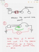
But there is no current flowing common mode in my first drawing which is what the OP was talking about. So how does a common mode choke work in this situation?
If the headphone end and the gone end coupled to ground capacitively I could imagine a common mode loop current at HF being possibility, but it would be minuscule and hardly a candidate for audibility when you have SMPS’s all over the place.
Draw it out so the mechanism can be seen.
If the headphone end and the gone end coupled to ground capacitively I could imagine a common mode loop current at HF being possibility, but it would be minuscule and hardly a candidate for audibility when you have SMPS’s all over the place.
Draw it out so the mechanism can be seen.
When people hear some audible effect, they don't necessarily know the cause although they may assume they do. People are constantly jumping to conclusions about things prematurely.
See here: A machine for jumping to conclusions
See here: A machine for jumping to conclusions
You cited a published research finding after posting "Please see Ioannidis: Why Most Published Research Findings Are False"
JN made an interesting point (certainly opened my thinking!) years ago, in the BT thread days, that stereo pairs of coaxial cables, signal grounded on both ends, don't have the textbook external noise immunity of textbook coaxial cables because half of the "return" current flows though each of the presumed identical cable's outer conductors. That seems likely the case in some headphone cables, although I know of several exceptions.
All good fortunes,
Chris
All good fortunes,
Chris
But there is no current flowing common mode in my first drawing which is what the OP was talking about. So how does a common mode choke work in this situation?
If the headphone end and the gone end coupled to ground capacitively I could imagine a common mode loop current at HF being possibility, but it would be minuscule and hardly a candidate for audibility when you have SMPS’s all over the place.
Draw it out so the mechanism can be seen.
I thought the claim was clamping a ferrite filter on a headphone cable changed the sound.
Where I think we are not communicating is that with a pair of wires that are not twisted into a nonlinear granular magnetic material their is a small field produced by each conductor that is not fully cancelled by transformer action.
By "transformer action" do you mean the differential input of a floating load?
Much thanks,
Chris
Much thanks,
Chris
By "transformer action" do you mean the differential input of a floating load?
What kind of headphone cable are we talking about? Bonsai showed a three wire L/R/G, mine have a TRS connector wired as two separate ground(shield)/signal wires.
By "transformer action" do you mean the differential input of a floating load?
Much thanks,
Chris
A very effective audio filter is to use an audio transformer in series with a balanced line. With a 1:1 transformer wired with the primary in series with one conductor and the secondary in series with the other. If you get the phase between them right then any signal that passes through the primary is then non inverted and placed in series with the other conductor. As the second conductor carries the inverse signal, the transformer signal cancels it.
That is how many differential mode filters work. (A capacitor across differential signal also causes loss and some filters use those or a combination of the two among other approaches.)
In the ferrite clamped on a headphone cable there can be some of that action, but the mechanism is that ferrite is a lossy magnetic medium and effectively causes an increased loss in signals that couple to it.
A semi-model for that would be a transformer primary in series with the conductor and the secondary connected to a resistor.
Last edited:
What kind of headphone cable are we talking about? Bonsai showed a three wire L/R/G, mine have a TRS connector wired as two separate ground(shield)/signal wires.
Using a common wire in the cable results in crosstalk due to the common wire resistance. It also has the problem of how do you split out the cable to each driver. So as it is a silly thing to do and this is the audio world folks probably do use a common conductor sometimes!
- Home
- Member Areas
- The Lounge
- The Black Hole......