I agree totally. Just swapping OPamps is stupid bussyness.
I can make an NE5534A sound great and an AD797 terible.
Distortion, bandwidth, noise etc. in modern OPamps are so good when implemented correctly that they have minimal influence on the sound.
I call that transparancy but that is not always what is desirable. I have eleborated on that earlier.
So what can go wrong ? : Oszilation, uncompensated high DC offset, noise on the groundline, noise from the PSU, thermal distortion, higher ouput voltage then the chip alows, poor decoupling, poor grounding, current limiting, instabilty of feedback loops due to unsufient open loop compensation to mention only a few traps you can fall into.
The classic is to use the NE5534A in circuits with very low gain without the compensation cap between Pin1 and Pin8.
Well said.
You have enticed me to be back here. I love to put my work aside...
I still have a number of puzzles yet to be sorted out. What is special about this thread is that we have a few experts here willing to guide the newbies, an opportunity that can not be missed.
You mentioned bypass. I understand that almost every opamp datasheet recommends using a 0.1uF ceramic (or film) capacitor right at the opamp supply pin. Also a tantalum or 10uF electrolytic capacitor can be useful.
However, I have not been able to implement that successfully. I have tried many times putting a 1uF / 0.1uF / 0.056uF / 0.01uF at the opamp supply pins and I could see up to a few hundreds mV ripples on my oscillioscope from a few hundred Hertz to 20MHz depending on various parameters. Using a high ESR 10-47uF does not have the problem, but they don't provide the low impedance return path at higher frequencies.
My understanding is this: Power supply regulators are usually inductive at the output. Wires from the regulator output to the opamp pins have inductance. It always forms some LCR resonant circuit unless the R is sufficient to damp the resonance. Some people recommend adding RC filters. However, adding R to power supply lines increases power supply impedance hence noise on the rails. By the way, the impedance of capacitors are not really very low, regardless of low ESR or not. I have tried RC filters, or simply adding R in series to the bypass capacitors. This can clean up the rails and make it appear to be quiet when there is no music signal, however, due to the increased power supply impedance the sound is not "transparent" to me.
A quick drawing with LTSpice shows what I mean. Consider 5cm wire to the opamp power pins. 5cm is not very long. The modelled result is not too different from what I see from my measurements.
An externally hosted image should be here but it was not working when we last tested it.
The PSRR of the opamps drops to low level at higher frequencies. So all those noise from the rails come directly at the signal output. No wonder not many people like opamps! I also wonder how many people are listening to opamps without resonance on the rails.
Failed finding a "bypass" solution, I turned to another method of trying to overcome the problem without using any rail local bypass at all.
I found a shunt regulator with an impedance plot like this. In real life, it may not be as low as that but I believe it should be very close. Wire resistance and inductive reactance dominate the output impedance.
For all other regulators I tried, if I put a low ESR cap, e.g. 0.1uF film at the output the regulator will resonate wildly. Not this one. It is the only one that demands some low ESR film caps at the output.
The regulator has been evolving since 12 months ago. You can find it here: http://www.diyaudio.com/forums/power-supplies/153715-my-take-discrete-shunt-voltage-regulator.html
Failed finding a "bypass" solution, I turned to another method of trying to overcome the problem without using any rail local bypass at all.
I found a shunt regulator with an impedance plot like this. In real life, it may not be as low as that but I believe it should be very close. Wire resistance and inductive reactance dominate the output impedance.
An externally hosted image should be here but it was not working when we last tested it.
For all other regulators I tried, if I put a low ESR cap, e.g. 0.1uF film at the output the regulator will resonate wildly. Not this one. It is the only one that demands some low ESR film caps at the output.
The regulator has been evolving since 12 months ago. You can find it here: http://www.diyaudio.com/forums/power-supplies/153715-my-take-discrete-shunt-voltage-regulator.html
In comparison to what impedance bypass capacitor can offer, I am attaching a graph from the datasheet for Vishay MKP 416 series capacitors. These capacitors are made for high frequency use.
We can see the impedance is an order of magnitude higher than the shunt regulator output impedance under 100kHz.
An externally hosted image should be here but it was not working when we last tested it.
We can see the impedance is an order of magnitude higher than the shunt regulator output impedance under 100kHz.
This is my implementation of the tweeter circuit (only a wiring guide to be used to build on veroboard, not real PCB).
I designed the PCB in such a way that the outputs of the regulator MOSFETs are as close to the opamp rails as possible. For the longest wire (+rail), the maximum length is 60mm between the regulator MOSFET and the (last) opamp supply pin.
At 20kHz 60mm 16 gauge wire has a resistance of 0.79mR, inductance of 51nH and reactance of 6.8mR. The impedance is definitely lower than what a 0.1uF capacitor can offer. If an opamp draws 1mA current, a ripple of 0.0068R x 0.001A = 6.8uV developed. I don't think this is audible. If I use remote sensing (i.e. using a sensing bridge, which I do), this number will even be much reduced.
Now consider a normal regulator of higher output impedance where long wires are run and a low impedance is only achieved via local bypass capacitors. Let us simplify it by assumming the impedance to be 0.1R at 20kHz. The ripple would be 0.1R x 0.001A = 1mV, 147 times (22dB) greater than the previous example. I think in this case the effect is audible, because most opamps don't have a PSSR (neg rail) higher than 70dB at 20kHz.
An externally hosted image should be here but it was not working when we last tested it.
I designed the PCB in such a way that the outputs of the regulator MOSFETs are as close to the opamp rails as possible. For the longest wire (+rail), the maximum length is 60mm between the regulator MOSFET and the (last) opamp supply pin.
At 20kHz 60mm 16 gauge wire has a resistance of 0.79mR, inductance of 51nH and reactance of 6.8mR. The impedance is definitely lower than what a 0.1uF capacitor can offer. If an opamp draws 1mA current, a ripple of 0.0068R x 0.001A = 6.8uV developed. I don't think this is audible. If I use remote sensing (i.e. using a sensing bridge, which I do), this number will even be much reduced.
Now consider a normal regulator of higher output impedance where long wires are run and a low impedance is only achieved via local bypass capacitors. Let us simplify it by assumming the impedance to be 0.1R at 20kHz. The ripple would be 0.1R x 0.001A = 1mV, 147 times (22dB) greater than the previous example. I think in this case the effect is audible, because most opamps don't have a PSSR (neg rail) higher than 70dB at 20kHz.
Last edited:
But in any case, I really wish I can stick a 0.1uF ceramic / film capacitor at the opamp supply pin without seeing any resonance.
I am really curious about how you guys do it without using some R in series to the rail or to the bypass capacitor.
More importantly, any problems you found with my implementation? Your critical comments will be very much appreciated.
I still have worries. For example, being a shunt regulator the MOSFET runs hot even heatsinked. With 16aug wire it may transmit the heat to the opamps. Do you think this to be a problem?
Last edited:
Have you tried removing the opamps (really) and fitting a small resistor across where pins 4 and 8 are (to draw the current the opamp draws) and repeating your measurements.
The question is... are the opamps the cause... or is the PSU the problem.
What amplitude are these oscillations on the scope ?
The question is... are the opamps the cause... or is the PSU the problem.
What amplitude are these oscillations on the scope ?
Also just as with amplifiers, the grounding and your points of reference become important.
A discrete regulator needs a star ground type reference just as does an amp, and the output can only be referenced to that one point.
That is a plus point for three terminal regs, the ground leg is "all in one place" and easy to work with.
If you take a 100% perfect reg and a 7812, by the time both have fed down a few cm of print the advantages of the "perfect" reg are diminishing fast for a "linear" load such as supplying opamps. For a dynamic load the situation is reversed.
This thread shows some practical scope pictures, and my way of testing regs using a pulsed current load... which started around post 34 ish.
http://www.diyaudio.com/forums/power-supplies/126929-low-cost-regulator-between-jung-flea.html
Have you tried removing the opamps (really) and fitting a small resistor across where pins 4 and 8 are (to draw the current the opamp draws) and repeating your measurements.
The question is... are the opamps the cause... or is the PSU the problem.
What amplitude are these oscillations on the scope ?
I haven't tried that exactly. I did try resistor load (without local capacitors) and I never found any problems with resistor load. With opamp there was a problem. There seem to have some pF range input capacitance associated with opamps.
If it's a real effect you have to determine the cause.
Are the opamps oscillating and modulating the supply. You could even try "slugging" the opamps in situ... such as grossly overcompensate to kill any possible instability and see if anything changes.
Also measure along the ground tracks and see if anything shows there.
You can also connect the scope probe leads together (probe tip and ground lead) and make sure the trace is noise free. Then keeping the two shorted touch on the ground track on the PCB and see if any noise appears on the scope.
Also just as with amplifiers, the grounding and your points of reference become important.
A discrete regulator needs a star ground type reference just as does an amp, and the output can only be referenced to that one point.
That is a plus point for three terminal regs, the ground leg is "all in one place" and easy to work with.
If you take a 100% perfect reg and a 7812, by the time both have fed down a few cm of print the advantages of the "perfect" reg are diminishing fast for a "linear" load such as supplying opamps. For a dynamic load the situation is reversed.
This thread shows some practical scope pictures, and my way of testing regs using a pulsed current load... which started around post 34 ish.
http://www.diyaudio.com/forums/power-supplies/126929-low-cost-regulator-between-jung-flea.html
I use Kelvin sensing (Four-terminal sensing - Wikipedia, the free encyclopedia) with the regulator. The voltage / ground reference are the sensing points, which are directly at the opamp supply pin and the load ground.
I read that thread. Your work is amazing. I have never gone as far as you do and this was the "dynamic test" I did: I played music on a CD player, connected the CD output to my preamp, turned on the CD player, and put the oscilliscope probe at the rail for the opamp. With the above mentioned regulator, I saw nothing but a straight, static thin line from 20Hz to 20Mhz, unlike the input signal that was dancing crazy.
No local bypass.
If it's a real effect you have to determine the cause.
Are the opamps oscillating and modulating the supply. You could even try "slugging" the opamps in situ... such as grossly overcompensate to kill any possible instability and see if anything changes.
Also measure along the ground tracks and see if anything shows there.
You can also connect the scope probe leads together (probe tip and ground lead) and make sure the trace is noise free. Then keeping the two shorted touch on the ground track on the PCB and see if any noise appears on the scope.
Mooly, Good question.
The opamp was opa627, configured as a buffer with negative input connected to the output. I don't know if this can be further compensated.
For dirty grounds, yes I did what you have just said. Unfortunately, since two months ago I found noise appearing. I possibly partially damaged the ground wire. I have not had the time to read the stuff to find a fix. I don't think I have time now to fix that. I will leave it to perhaps next year.
The opamp was opa627, configured as a buffer with negative input connected to the output. I don't know if this can be further compensated.
Not really... not as such anyway.
Can you see the same noise component on the output of the opamp as well as the supply ?
Ferrite beads 🙂 You might find this interesting.
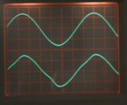
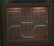
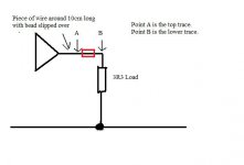
Pictures shows the output from an amp (TDA7293 in this case) driving a 3.3 ohm load at low level (3 volts or so pk/pk. The output from the IC connects to the load via 10cm or so of wire with a bead slipped over it. The wire was nicked either side of the bead to connect the probes. Top trace is the output side of the opamp, lower is the load.
The distortion produced depends strongly on the current flow in the wire, presumably the ferrite saturates at some level.
This is why at the front end of an opamp etc there is no problem using beads... that distortion is non existant as the currents are tens of thousands of times smaller.
Good 'innit.
😉
Attachments
Last edited:
Analog Devices has made a replacement for the OPA627. It is called the ADA4627.
I am currently testing it out. I do not know about a replacement for OPA637 though.
My bypass method is 2 bigger elcaps over the supply lines and a 0.1uF MKP direct from Pin 4 to Pin 7. I usually do not fit 2 0.1uF from supply line to ground because you dump the HF to ground. That can lead to dirty ground currents. I usullay avoid ceramics but they are getting better so in case you get oscillation with my arangement use aditional 2.2nF to 4.7nF COG/NPO. Some people do the 10 / 10 / 10 rule but that does not work as you see in some simulations here. So that whould be a 10uF elcap, a 1uF foil and a 0.1uF ceramic for example. The resonance frequencies of that arangement do not match very well. There is a paper from Texas intruments about bypassing, and i hope i can find it and post is here. With very fast Opamps they used surprisingly small value caps to avoid ozcialltion. I see the lokal elcaps i use more like current buffers and the 0.1uF does the HF bypass. Whan you can do is insert a small value resistor before the elcaps or a small value inductor. The Elcaps keep the lokal impedance low in that case.
I also tried to use the 2 elcaps for several OPs that are then lokally decoupled with the 0.1uF MKPs successfully.
As I have said on another thread, you actually making things worse by connecting directly between the rails.My bypass method is 2 bigger elcaps over the supply lines and a 0.1uF MKP direct from Pin 4 to Pin 7. I usually do not fit 2 0.1uF from supply line to ground because you dump the HF to ground. That can lead to dirty ground currents.
Using the ground for decoupling doesn't mean that you are not "pushing" something to the ground. Actually the HF current needs to be shorted between rail and ground by the decoupling caps, because that's the path it goes anyway (the way an OpAmp is working).
Leaving the ground not decoupled (read shorted for HF) leaves a path for the HF to leak back to PS.
Can you see the same noise component on the output of the opamp as well as the supply ?
Ferrite beads 🙂 You might find this interesting.
If I used a local bypass capacitor which created the problem as modelled in the previous page, I found the ripples in both the rail and the output, if my memory serves me.
As for my current set up shown in the previous page, i.e. relying on super low impedance regulator, short wires, remote sensing, no local capacitor bypass, both the rail and output are quiet.
Even with remote sensing, I found that the shorter the wire between the regulator and the opamp, the better it sounds.
My current test set up already sounds very good and very transparent, though I believe I can still hear some small amount of noise in the upper frequency range. I don't know where it comes from, grounding is the primary suspect. I need to fix something on the scope (probe) in order to see more clearly what is happening.
I hope I can find some answers here for the local bypass. Because, at very high frequncies the regulator I am using still won't beat a cheap ceramic cap. The regulator won't do anything above a hundred kHz. If high frequency components are present, I could still get into trouble. But until one day I have time to study the stuff (about measurements) it won't be easy for me to find an answer.
As I have said on another thread, you actually making things worse by connecting directly between the rails.
Using the ground for decoupling doesn't mean that you are not "pushing" something to the ground. Actually the HF current needs to be shorted between rail and ground by the decoupling caps, because that's the path it goes anyway (the way an OpAmp is working).
Leaving the ground not decoupled (read shorted for HF) leaves a path for the HF to leak back to PS.
What is your method of bypassing without getting resonance on rail as modelled in the previous page? I presume it is not adding "R".
Decoupling issues
How does that come about?
Can't follow your argument here. The path of current out of the opamp might be to ground, if there's a ground connected load. But if the output goes into the input of another opamp then there's no current to ground - in such a case, certainly no need for decoupling to ground. If there is a ground connected load, then the decoupling needs to go from the power supply pins by the shortest route to that load's ground; this ground needs to go via an entirely separate path back to the power supply and not be merged with the signal ground.
But power supply wires have inductance, so they won't be good at 'leaking HF back to the PSU'.
As I have said on another thread, you actually making things worse by connecting directly between the rails.
How does that come about?
Using the ground for decoupling doesn't mean that you are not "pushing" something to the ground. Actually the HF current needs to be shorted between rail and ground by the decoupling caps, because that's the path it goes anyway (the way an OpAmp is working).
Can't follow your argument here. The path of current out of the opamp might be to ground, if there's a ground connected load. But if the output goes into the input of another opamp then there's no current to ground - in such a case, certainly no need for decoupling to ground. If there is a ground connected load, then the decoupling needs to go from the power supply pins by the shortest route to that load's ground; this ground needs to go via an entirely separate path back to the power supply and not be merged with the signal ground.
Leaving the ground not decoupled (read shorted for HF) leaves a path for the HF to leak back to PS.
But power supply wires have inductance, so they won't be good at 'leaking HF back to the PSU'.
My current test set up already sounds very good and very transparent, though I believe I can still hear some small amount of noise in the upper frequency range. I don't know where it comes from, grounding is the primary suspect. I need to fix something on the scope (probe) in order to see more clearly what is happening.
I hope I can find some answers here for the local bypass. Because, at very high frequncies the regulator I am using still won't beat a cheap ceramic cap. The regulator won't do anything above a hundred kHz. If high frequency components are present, I could still get into trouble. But until one day I have time to study the stuff (about measurements) it won't be easy for me to find an answer.
Try powering with batteries just to see what happens.
hi guys, long time no see 🙂
sad to see Andrea got tanked, he's not a bad guy...just a little obsessed 😀
anyway, I currently use LT1028AC in my "Firestone Spitfire" DAC and I looooooove it, my favorite opamp ever!
here's what Ray Samuels has to say about it: REVIEW: Ray Samuels Emmeline HR-2 - SGHeadphones
but I'm getting a tube amp: Tube Headphone Amp - Little Country III Tube Headphone Amplifier
it's got an OPA2604AP exclusively used for "DC servo"...does it even matter that I swap it? many ppl tell me that if an opamp is not used in AC, then it won't color the sound AT ALL?
Thanks for any insight,
PS: http://www.prodigy-pro.com/diy/index.php?topic=20477.0;wap2
sad to see Andrea got tanked, he's not a bad guy...just a little obsessed 😀
anyway, I currently use LT1028AC in my "Firestone Spitfire" DAC and I looooooove it, my favorite opamp ever!
here's what Ray Samuels has to say about it: REVIEW: Ray Samuels Emmeline HR-2 - SGHeadphones
As Mr. Samuels once remarked, the LT1028 is like putting sugar all over your sound. It has a very liquid, sweet, and warm midrange that exhibits sharp bass and treble roll off. Unlike the Analog Devices op-amps, it is not dark. In fact, low level details flow through with greater clarity and definition.
but I'm getting a tube amp: Tube Headphone Amp - Little Country III Tube Headphone Amplifier
it's got an OPA2604AP exclusively used for "DC servo"...does it even matter that I swap it? many ppl tell me that if an opamp is not used in AC, then it won't color the sound AT ALL?
Thanks for any insight,
PS: http://www.prodigy-pro.com/diy/index.php?topic=20477.0;wap2
After listening for an hour and switching from servo to non servo and back for at least 100 times, I can say that I couldn't detect any difference in sound between the two
Last edited:
If it's used as a servo then you are looking to use opamps suited for DC precision, and that means offering high input impedance... the OPA2604 is mediocre for the first (DC precision) but being FET input has a very high impedance.
It's all relative though... would have to see a circuit to see just how it's used.
Why does a tube amp need a servo ? are the outputs somehow DC coupled ?
or is it used for maintaining correct bias.
Don't worry... the OPA2604 will be fine. And yes, from what you describe it doesn't have any influence on the sonics as such.
- Home
- Amplifiers
- Chip Amps
- The best sounding audio integrated opamps