change the ratio of R5:R6 to see what happens when Mooly tells you to adjust the attenuator.
Try R5=1k0 and R6=19k.
Try R5=19k and R6=1k0.
Try R5=19k9 and R6=100r.
compare the three RF attenuations.
Now add a tiny inductance before each interconnect Cpara. Try 10nH.
This will create three cascaded 2pole RF attenuators.
Compare the RF attenuation.
Put one of the 10nH before the 1000p at the RCA.
Compare the RF attenuation.
Change the 1000p to 47pF
Compare the RF attenuation.
Change all the inductances to 100nH.
compare the RF attenuation.
I think you should be aimimg for F-1dB >=100kHz for inaudibility.
Last edited:
Replace the stacked film low inductance 68pF PP with a rolled foil medium inductance 100pF PS and the filter characteristics will be changed. This may be audible. In addition the RC becomes 0.58us. This slope is modified by the inherent inductance of the polystyrene.
I am not talking about swapping boutique /exotic parts for technically competent components. I am talking plain and simple engineering.
Andrew, you are talking in purely theoretical terms (which is fine), but I think sometimes you look to hard for problems that just aren't there.
When you are dealing with RF as opposed to audio then it becomes a whole different ball game... the shape of conductors, thickness off etc, plus all the other things that you never give a moments thought to in audio. Such things as the transmission of RF through RCA connectors for example... which behave as anything but a perfect connector at higher frequencies... (and RF is such a broad term term... you have to be more specific in what frequencies you mean).
Do you have any practical measurements, results etc for the suggestion of using different construction caps and their effect on the filter response and their effect as an RF filter.
It's just a non problem.
change the ratio of R5:R6 to see what happens when Mooly tells you to adjust the attenuator.
Try R5=1k0 and R6=19k.
Try R5=19k and R6=1k0.
Try R5=19k9 and R6=100r.
compare the three RF attenuations.
Now add a tiny inductance before each interconnect Cpara. Try 10nH.
This will create three cascaded 2pole RF attenuators.
Compare the RF attenuation.
Put one of the 10nH before the 1000p at the RCA.
Compare the RF attenuation.
Change the 1000p to 47pF
Compare the RF attenuation.
Change all the inductances to 100nH.
compare the RF attenuation.
I think you should be aimimg for F-1dB >=100kHz for inaudibility.
Andrew,
I did all those before I put the 1nF at the RCA jack. I understood it was not the proper way but it was purely a test to check if an RF shunt changed the sound or not. Moving it to the RCA jack eliminated the possibility of the troublesome 34pF at the +/- inputs of the opamps.
See below. I have added the inductance approximate to the interconnect lengths and set the volumn pot at 12k//8k (normal listening level), 19k//1k and 1k//19k. No significant high frequency rolloff. Again, I listen to music at around 12k//8k level.
Regards,
Bill
An externally hosted image should be here but it was not working when we last tested it.
Concerning the sensitivity of the human ear to frequencies over 20kHz a Japanese research team measured brain activity some years ago.
They measured activity in certain aereas when high frequency signals where present even when the signal was not directly correlated with the music as far as i can remember.
There was an AES paper about that. I hope i can find it.
They measured activity in certain aereas when high frequency signals where present even when the signal was not directly correlated with the music as far as i can remember.
There was an AES paper about that. I hope i can find it.
I can't read the attenuation plots, but it looks like there is over a decade of movement in the RF roll-off frequency.
Now remove that 1000pF and put back in the 1k+68pF
Now remove that 1000pF and put back in the 1k+68pF
1nf is too high to use on the output of an opamp (in practice).
Mooly,
Sorry for the confusion: The CD player opamp in the drawing does not exist in real life. It was a convenient thing for modelling a circuit. The Marantz SACD player uses HDRM or something. In any case, there is a 200R series resistor at the output of the HDRM first, then the output capacitor, then a series 50R, and a shunt 1000k to ground.
Let us say the CD output is an opamp connected to a series 200R resistor. In that case, would the 200R be sufficient to damp any possible overshoot / undershoot on a 1nF load?
Regards,
Bill
Last edited:
I can't read the attenuation plots, but it looks like there is over a decade of movement in the RF roll-off frequency.
Now remove that 1000pF and put back in the 1k+68pF
Andrew,
I am happy to hear your comments. It is done as requested. 🙂
I am not interested in whether the roll-off point is optimal or not, because it is not difficult to get the roll-off point right. The concern is that it does not affect the audioband. Clearly, it does not.
Regards,
Bill
Edit: Opps, I should have added a buffer in the middle to get more accurate curves but never mind.
An externally hosted image should be here but it was not working when we last tested it.
Last edited:
either change R2 to 250r or add in the extra 200r series resistor.there is a 200R series resistor at the output of the HDRM first, then the output capacitor, then a series 50R, and a shunt 1000k to ground.
It won't make much difference, but 250r and 1000pF without any of the other RF attenuators gives RC=0.25us.
Let us say the CD output is an opamp connected to a series 200R resistor. In that case, would the 200R be sufficient to damp any possible overshoot / undershoot on a 1nF load?
It's OK I suppose, 1000pf at 20khz has a reactance of around 8k ohms... most opamps will drive that.
I'm losing the plot a little bit here, your latest simulation has more coils and caps and potential interactions than a front end for multiband tuner lol.
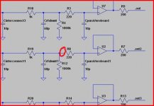
If you suspect RF is entering the chain, one of the most effective quick fixes is to slip a ferrite bead over a resistor feeding the input to the first stages.
Shown in red here on one stage.
Attachments
Mooly,
Adding more coils and caps in the simulation was done for Andrew on his request.
Sounds like a good idea which made me spend the last 2 hours studying and researching the use of ferrite beads, as I have never paid attention to them.
I have not found many cases using them in the audio signal though, in PSU a bit more common. On the negative side, I have found this:
EDN PDF
It comes from the article:
Testing your notebook design for audio fidelity - 5/13/2008 - EDN
Regards,
Bill
I'm losing the plot a little bit here, your latest simulation has more coils and caps and potential interactions than a front end for multiband tuner lol.
Adding more coils and caps in the simulation was done for Andrew on his request.
If you suspect RF is entering the chain, one of the most effective quick fixes is to slip a ferrite bead over a resistor feeding the input to the first stages.
Sounds like a good idea which made me spend the last 2 hours studying and researching the use of ferrite beads, as I have never paid attention to them.
I have not found many cases using them in the audio signal though, in PSU a bit more common. On the negative side, I have found this:
EDN PDF
It comes from the article:
Testing your notebook design for audio fidelity - 5/13/2008 - EDN
Regards,
Bill
Hi Bill,
I think the links you posted are referring to using a bead or ferrite component on an "output" line such as a headphone output etc... or even a speaker feed. Doing that does cause a rise in distortion, something I have experienced first hand, and the effect is massive at higher powers.
Adding a bead to an input (certainly as far as I know), causes no such issues. It's an ancient technique, used in many commercial products too in one form or another. On a discrete amp it can be a bead slipped round the base of the first transistor etc.
if you are not comfortable with all the extra components then take them out. It was a way of comparing the basic frequency response to one with lots of parasitics. Remove them all and see how it changes.Adding more coils and caps in the simulation was done for Andrew on his request.
It's understanding the changes that is going to teach you what the various components are doing.
Thank you very much guys, Mooly, Andrew, Joachim, auddoc and others.
I really learnt a great deal from you guys in the past a few days.
Your posts and answers led me to sort out some of the stuff I did not understand previously. After a few years learning from the diyForum (I spent most of my time on open baffle speakers) I have to rush to get my project (mostly) finish at this stage and stop DIY for a year or so in order to make some major work commitment. After these a few days I now feel I can start my final build. I am confident that in 2 weeks time I will have a excellent system running. I will come back and learn more from you guys some time in the future.
All the best and very best regards,
Bill
To answer an older post about the OPA627 against the OPA827.
I tried the OPA827 in one of my phonostages.
Results where very good and i think this is an upgrade over the OPA134, both in measurements and in sound.
I did not directly compare the OPA827 to the OPA627. That comparison was done by some Japanese friends i trust. They used both chips as an I/U converter in a DAC and they prefered the OPA827.
Good information. I received a note from a friend at dinner time today and he wrote:
This is audio DIY. 🙂
There are so many factors that can influence the result - 1) whether it is implemented properly; 2) what application? in a DAC or in the analogue section? 3) what conditions? 4) what PSU? 5) subjective preference 6)...
Ultimately, if you can measure it, you are probably closer to the truth.
Looking forward to your test result.
opa627 is quite a benchmark design. I recently tried a opa 827 against opa 627 replacing the opamp in a Quad 405 and the opa627 is the better device..
This is audio DIY. 🙂
There are so many factors that can influence the result - 1) whether it is implemented properly; 2) what application? in a DAC or in the analogue section? 3) what conditions? 4) what PSU? 5) subjective preference 6)...
Ultimately, if you can measure it, you are probably closer to the truth.
Looking forward to your test result.
I agree totally. Just swapping OPamps is stupid bussyness.
I can make an NE5534A sound great and an AD797 terible.
Distortion, bandwidth, noise etc. in modern OPamps are so good when implemented correctly that they have minimal influence on the sound.
I call that transparancy but that is not always what is desirable. I have eleborated on that earlier.
So what can go wrong ? : Oszilation, uncompensated high DC offset, noise on the groundline, noise from the PSU, thermal distortion, higher ouput voltage then the chip alows, poor decoupling, poor grounding, current limiting, instabilty of feedback loops due to unsufient open loop compensation to mention only a few traps you can fall into.
The classic is to use the NE5534A in circuits with very low gain without the compensation cap between Pin1 and Pin8.
Hi Bas!
I've been using a set of them (2 pair mounted in BrownDog-like adapters to replace LM833n's in a very heavily modified Philips CD player) for about 2 weeks now.
Overall, I'm pretty impressed. Nice depth, good detail, not over-etched, and nicely articulated bass.
I have both the ADA4627-1ARZ and ADA4627-1BRZ chips set up the same way. After extended break in and listening I prefer the BRZs.
Also been playing with 2 pair of OPA227u in the same arrangement. Still evaluating these.....🙂
HTH,
Dan
Dreaming of an OPA837...
Do you know of anyone who's tried the OPA637 (suitably re-compensated) as an I/V ? I only see people talking about the 627 in this context, but it definitely looks inferior to the 637 in the specs that matter for I/V (slew rate, settling time). Shame the 827 doesn't include a settling time vs accuracy plot as found in the 627/637 datasheet. The 827 error signal (fig 36-39) settling looks asymmetric from the time domain plots - doesn't bode too well - the positive step shows ringing but the negative one doesn't. What's bizarre is that this ringing is evident on both steps for the non-inverting connection (fig32), but they don't say which configuration they tested.
What would be really cool would be TI releasing an OPA837 as a decompensated version to allow more end-user optimisation.😀
They used both chips as an I/U converter in a DAC and they prefered the OPA827.
Do you know of anyone who's tried the OPA637 (suitably re-compensated) as an I/V ? I only see people talking about the 627 in this context, but it definitely looks inferior to the 637 in the specs that matter for I/V (slew rate, settling time). Shame the 827 doesn't include a settling time vs accuracy plot as found in the 627/637 datasheet. The 827 error signal (fig 36-39) settling looks asymmetric from the time domain plots - doesn't bode too well - the positive step shows ringing but the negative one doesn't. What's bizarre is that this ringing is evident on both steps for the non-inverting connection (fig32), but they don't say which configuration they tested.
What would be really cool would be TI releasing an OPA837 as a decompensated version to allow more end-user optimisation.😀
- Home
- Amplifiers
- Chip Amps
- The best sounding audio integrated opamps