I think the decibal scale on the left fooled me from what I am used to see on transfer graphs. Sorry about that...😱
OK, here is the real measured and photographed effect of Bills 100 ohm + 68pf network.
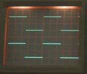
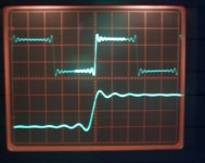
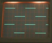
Top trace is the "input" to the 12K + 8K "volume control" and the lower is the output at the junction "wiper" of the network.
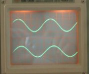
First up for reference is 1khz and no cap, then 1khz with the cap. Then we have 10 khz with and without the cap and finally 20khz with cap... the top trace in all these shows the same as "no cap" anyway.
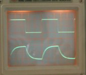
Now before you all get excited and say that the 10 and 20khz shows some roll off and limited rise time due to the cap remember to put this in perspective. So finally here again is the shot of how CD (any player) reproduces a 1khz square wave within the confines of a strictly limited bandwidth of around 20khz that the CD specification imposes.
Pictures got a little out of order 🙂
So the effect of this RC network I don't feel can be audible as such... if it's really changing the sound as much as you say then something else is going on. You can't even really say that the effect would cause a loss of HF energy over several octaves as the reduction across the audio band (and well beyond) is just to small.
Dunno Bill 😉... you are going to have to measure for real your set up and confirm and identify what's really happening.
Top trace is the "input" to the 12K + 8K "volume control" and the lower is the output at the junction "wiper" of the network.
First up for reference is 1khz and no cap, then 1khz with the cap. Then we have 10 khz with and without the cap and finally 20khz with cap... the top trace in all these shows the same as "no cap" anyway.
Now before you all get excited and say that the 10 and 20khz shows some roll off and limited rise time due to the cap remember to put this in perspective. So finally here again is the shot of how CD (any player) reproduces a 1khz square wave within the confines of a strictly limited bandwidth of around 20khz that the CD specification imposes.
Pictures got a little out of order 🙂
So the effect of this RC network I don't feel can be audible as such... if it's really changing the sound as much as you say then something else is going on. You can't even really say that the effect would cause a loss of HF energy over several octaves as the reduction across the audio band (and well beyond) is just to small.
Dunno Bill 😉... you are going to have to measure for real your set up and confirm and identify what's really happening.
Attachments
Last edited:
Mooly,
Wow, Thanks a million for taking your time doing and posting those. I am indeed excited.
However, I have not been able to understand them fully.
First did you mean 1k + 68p instead of 100 ohm + 68p after a 20k pot? Or, does your circuit contain 20k pot, or a resistor divider of 12k + 8k, plus 1k and 68p? - If a 20k divider is in the front then it does not matter much if it is 1k or 100 ohm anyway.
Secondly, is the top trace produced by one channel of the scope connected to the "input", and the bottom trace by another channel connected to the output, i.e. top of the 68p? So what is the exact meaning of "the top trace in all these shows the same "no cap" anyway"? The cap will still inflence the input, only with a corner frequency higher depending on the voltage divider values.
If the top trace is "no cap" and generates perfect square wave, do we see that the bottom traces are distorted, except picture 3 (10k with cap?)
How come picture 2 (1khz with cap) shows inperfect SW, picture 3 (10khz with cap) shows perfect SW, picture 4 (10khaz without cap) shows inperfect SW?
Does the last picture show the input and output of a CD player fed with perfect 1kHz SW? I failed to see any abnormalties. By the way, I have a collection of SACDs and they go much higher than 20kHz according to the SACD players specs. Indeed, when I do my subjective tests I use SACD mainly.
In any case, I trust objective measurements a lot more than subjective evaluations. But first I need to understand those pictures.
I very much hope your tests prove that I am wrong. Because in that case, I find the truth and will use the proper design in my circuits.
Regards,
Bill
Thanks to the internet for connecting us together. Unfortunate the internet does not connect us in time. When you guys are active over in Europe we get sleepy here. It is 11:34pm at night. I will check your posts first thing in the morning tomorrow.
By the way, I only noticed your "Similation Free" tonight. If I did notice it earlier I would not have posted my simulations. Sorry.
By the way, I only noticed your "Similation Free" tonight. If I did notice it earlier I would not have posted my simulations. Sorry.
Last edited:
Newbie on opamp here.
I have a phonostage with JRC5534 and wants to replace it (sounds quite harsh to me).
Would an OPA134 or LT1028ACN8 be a drop in replacements?
Thanks.
I have a phonostage with JRC5534 and wants to replace it (sounds quite harsh to me).
Would an OPA134 or LT1028ACN8 be a drop in replacements?
Thanks.
Hi Bill,
A confession... I used 100 ohm... don't ask me why, I scribbled the circuit down correctly... and thought I'd remembered it correctly as 100 ohm. duh 🙂
Anyway, the effect of changing the 100 ohm to 1k has no effect that you could see in a picture... the result is the same... and yes I tried it for real. Had it been different I would have repeated the shots, but there's no point, the difference was to microscopic to show in a picture.
What I did do while I was trying that (with the 1k) was measure the -1db point. I say measure because this is a real result taking into account the scope probe capacitance which adds to the 68 pf cap anyway (It's only a few pf for a 10 to 1 probe).
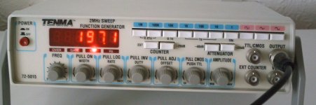
I set the voltage to 4 volts across the 68 pf cap at 1 khz and the output fell to 3.55 volts at around 197khz 🙂 I'm working in peak to peak measurements on the 'scope but of course if you convert to RMS it's the same.
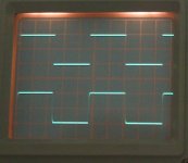
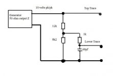
This picture should clarify the measurements. The generator output is 50 ohm. I used an 8k2 rather than 8 k. Top trace is always the output of the generator. The bottom trace is the voltage across the 68pf cap... the signal that you are feeding to the opamp.
Edit... In all the shots above in the earlier post the pictures appeared out of sequence for some reason... if you hover your cursor over each then the description should appear... it does in IE8 anyway lol. If not this is the correct description/order.
That was confusing, sorry.
First piccy is 1k and no cap.
Second is 10k with cap.
Third is 10k and no cap.
Fourth is 20k with cap.
Fifth is the CD
Sixth is 1K with cap.
A confession... I used 100 ohm... don't ask me why, I scribbled the circuit down correctly... and thought I'd remembered it correctly as 100 ohm. duh 🙂
Anyway, the effect of changing the 100 ohm to 1k has no effect that you could see in a picture... the result is the same... and yes I tried it for real. Had it been different I would have repeated the shots, but there's no point, the difference was to microscopic to show in a picture.
What I did do while I was trying that (with the 1k) was measure the -1db point. I say measure because this is a real result taking into account the scope probe capacitance which adds to the 68 pf cap anyway (It's only a few pf for a 10 to 1 probe).
I set the voltage to 4 volts across the 68 pf cap at 1 khz and the output fell to 3.55 volts at around 197khz 🙂 I'm working in peak to peak measurements on the 'scope but of course if you convert to RMS it's the same.
This picture should clarify the measurements. The generator output is 50 ohm. I used an 8k2 rather than 8 k. Top trace is always the output of the generator. The bottom trace is the voltage across the 68pf cap... the signal that you are feeding to the opamp.
Edit... In all the shots above in the earlier post the pictures appeared out of sequence for some reason... if you hover your cursor over each then the description should appear... it does in IE8 anyway lol. If not this is the correct description/order.
That was confusing, sorry.
First piccy is 1k and no cap.
Second is 10k with cap.
Third is 10k and no cap.
Fourth is 20k with cap.
Fifth is the CD
Sixth is 1K with cap.
Attachments
Last edited:
Newbie on opamp here.
I have a phonostage with JRC5534 and wants to replace it (sounds quite harsh to me).
Would an OPA134 or LT1028ACN8 be a drop in replacements?
Thanks.
Yes
The harshness may not come from the Opamp but rather from non correct RIAA curve.
Many circuits i have seen have a bass loss and a treble rise so somebody should put your circuit into a simulator.
The OPA134 has even more distortion in the treble and the LT1028 is optimised for low impedance so when you have an MM cartridge with high impedance and high inductance it may not be the best choice for noise.
Here are two low distortion buffers. The discrete one is a further development of the
John Linley-Hood buffer. The darlingtons bootstrap the Fets and provide lokal feedback.
The trimmer trimms offset. It is not distortion free but very much better in that regard then the PSG buffer although with a spread of higher order harmonics. It is also very fast with a -3dB point of 15MHz. I use it quite often and like the result very much.
The second circuit is a simple OPamp buffer. The feedback resistor should idealy have the same value as the source impedance for lowest common mode distortion.
With the LME49710 distortion is very hard to measure. The other OPs mentioned are not much worce. As simple as that circuit is, with modern Opamps it´s hard to build a dircreet circuit that is technically better except you need extremely low noise or very high output voltage or current or both.
Attachments
Mooly,
Thanks for your clarifications of the photo sequence and your nice drawing. Yes 100R or 1k should make little difference.
However, I am not sure if we could logically come to the conclusion that the 1k + 68p is inaudible.
If your "with cap" and "without cap" graphs all show identical square waves then a conclusion can be drawn that the 1k + 68p is inaudible.
However, the situation is that, other than the 1k graphs showing identical square waves with and without caps, at 10kHz and 20kHz the "with caps" graphs clearly show distorted square waves. We can only come to the conclusion that the 1k + 68 has not introduced distortion at 1kHz, but we can not conclude that it has not introduce distortions at 20kHz, indeed, the opposite is true - we can conclude that the cap introduces distortions at 10kHz and 20kHz (but if the distortion component is purely phase shift then such distortion is inaudible).
We understand that the rolloff above 20kHz introduces some tiny phase shift below 20kHz, which (partially or fully) contributes to the distorted square waves. This is expected. We also understand that phase shift at these frequencies is not audible. However, we have not established that the distorted square waves all come from the phase shift alone, but nothing else, unless the measured distorted square waves match exactly to mathematically derived waves introduced by the exact amount of phase shift of the 1k + 68p at 10kHz, 20kHz.
I am not saying that the 1k + 68p introduce distortions other than the phase distortions, as I have no evidence to suggest that. In other words, your "inaudible" suggestion may come out correct. However, I am only doing LOGIC here, that based on the graphs we still can not conclude that the 1k + 68p has not introduced other distortions (on top of the inaudible phase distortion) at higher frequencies.
I am sure that this argument is not for argument's sake. As said I hope I am proven wrong. I admire your objective approach. I fully understand that human perceptions can not be fully trusted... (I don't want to go into discussion of another discipline). Having spent 7 years doing science at Universities should put me into the objective camp not the subjective camp in the audio hobby. I have not really studied electronics though.
But I heard that different capacitors do make a big difference to sound! Do I belong to the subjective camp?
I wish I could have the time to do further investigations. Perhaps when I have the time, I will get a better signal generator and scope to examine every node in my circuits.
By the way, if you are familiar with opamp circuits, would you mind spending a couple of minutes to briefly go through the 3 filter circuits I posted and let me know if anythings are obviously wrong?
Many Thanks and Best regards,
Bill
Mooly,
One more question if you don't mind.
If the signal does not contain high frequency components, would the compensation cap on the opamp necessary? I guess not, but think I had better ask the experts.
In my bandpass and low pass filters all the high frequency components are gone before the signal reach some opamps, so I am thinking that I could ditch the compensation cap, unless RF somehow gets in, such as the RF picked up from the air or induced from the rails.
Regards,
Bill
It is not distortion free but very much better in that regard then the PSG buffer although with a spread of higher order harmonics. It is also very fast with a -3dB point of 15MHz. I use it quite often and like the result very much.
I like that - your obvious confession that you like some types of distortions. 🙂 Most of my audiophile friends love the 2nd order harmonics in their systems, but still vigorously depend their position that they don't like distortions and their systems sound real! I wish they had your honesty.
Can you tell us if you prefer the modified JLH circuit or the opamps?
How come among opa627, lm4562, AD825 and opa2134 I only like the sound of the opa627? Perhaps its higher PSSR and CMRR are doing the job. I have now a very quiet PSU and perhaps it is the time to redo the assessments.
Did you measure the distortions?
Best Regards,
Bill
The OPA627 was the lowest distortion Fet Opamp for quite a while. I use it in distortion magnifier circuits and as very high performance servos. One of the reasons it has lower distortion then the OPA134 is much higher open loop gain. See the spec sheets.
I have heard that it is now obsolete. A good replacement is the OPA827 that has even less distortion. Analog devices also made a replacement with slightly better specs : the ADA4627. I have it around and will build an amp soon to test it.
On ground of sound i like the modified JLH also because it makes servos in many circuits obsolete. Distortion is very low in that circuit. Two orders of magnitude better then the PSG. For Zerro distortion you need extremely high open loop gain though.
Another option for example a gain of 30dB is to stack three amplifiers with a gain of 10dB. Curiously as is may seem, more is less here. Scott Wurzer did a paper on that.
I have it somewhere in my files but please do not push me to find it. I am VERY bussy momentarily.
Under this ULR you can download a huge PDF file that has the most popular OPamps tested for distotion objectively. SG-Acoustics · Samuel Groner · IC OpAmps
It´s an amasing body of work. How they sound subjectively is an entirely different discsussion but having elctronics build that has " zerro distortion" teached me a lot.
Let me say only so much that no recording and no storage media is " perfect" not to mention room and speakers so some artfully thrown in distortion may actually enhance listening pleasure
ref post 1703 and post 1707
I assumed the Rs was 200r.
The RF filter does not have a source of 200r, I see 12k1//8k as the source resistance.
I also see the potential for parasitic capacitances between the passive attenuator and the next opamp.
The schematic omits all the parasitics, but allowing only for what is shown the RF filter is not 0.02us nor is it 0.08us.
It is >0.4us possibly much greater.
Adding or removing the 1k0 will make a significant difference.
Swapping out a 68PP and substituting a 100PS will make a difference.
I cannot hear the difference between 0.33us RF filter and 0.7us but some builders say they can and insist that 0.33 is the lowest they find acceptable.
I suspect you are hearing a genuine difference by changing those components.
Part of the reason for this unexplainable audibility is that you have misunderstood the RF filter and what affects it and it's audibility and you were unable to describe correctly what your experiment amounted to.
Newbie on opamp here.
I have a phonostage with JRC5534 and wants to replace it (sounds quite harsh to me).
The 5534 doesn't have inherent harshness - if it did then almost anything sent through a traditional analogue console (think Neve or SSL) would have bucketloads of harshness simply because each channel has dozens of them. So I'd say its far more likely that the harshness comes from the power supply or is a result of poor layout or circuit design. Simply substituting another opamp won't fix those problems.
Its possible the designer is trying to get too much gain out of a single device, that could lead to harshness. In which case substituting a 1028 which has higher GBW will mitigate this. However it could also lead to higher output noise as the 1028 is designed to work with very low impedances to maintain its ultra-low voltage noise spec. As a consequence of its low voltage noise, its current noise is considerably higher than a 5534.
HF rejection
Let's say for arguement's sake, that you want your audio system to have the widest bandwidth that is available.....oops, at several hundred kilohertz you start encountering the lower end of the RF range. while your system may not play this back, and certainly not your speakers.or you can't actually hear it...the idea is that the stuff before that (preamps, amplifiers, etc)may become saturated with HF information outside of the band of hearing, possibly even clipping and causing harmonics above and below the fundamental frequencies of the RF. Harmonics don't just go up.......Can it (the harmonic distortion) affect the stuff in the audio range? That's what the arguement may be about.
In my point of view you may need an audio system bandwidth of about 100 to 150kHz. At least 5 times the range of your actual hearing limit, of 12kHz to 20kHz, depending on hearing damage and the effects of old age, on your actual ear/ brain bandwidth. If an opamp is already saturated with HF signals, it is in clipping mode, which causes tons of distortion products, albeit in the HF/RF area. Is the lower frequency information affected while this is happening? The standard wisdom would say Yes!!!!......consider a wide bandwidth power amplifier that is swamped with RF and kills the tweeters in your system- energy still gets delivered to the speakers and you won't even know it...that alone might be sufficient justification. Just because you can't hear it doesn't mean there is no effect. You can sure see it with an oscilliscope, I know I have.
Typically I use opamp bypass capacitor values calculated to about 150 kHz maximum bandwidth, for this reason.
A colleague of mine, in a major LA studio, used video op-amps to drive the busses on a huge custom-built 96 channel, 48 buss mixing console, because they will drive a very low 50 Ohm load, all day long, but had to limit the bandwidth because they would easily amplify computer generated RF, etc, out to the gHz region, for the reasons mentioned above..
Very good question , by the way. That's why audio electronics designers come in all shapes and sizes.
Most op-amp circuits require some kind of HF bypass. Why?Mooly,
One more question if you don't mind.
If the signal does not contain high frequency components, would the compensation cap on the opamp necessary? I guess not, but think I had better ask the experts.
In my bandpass and low pass filters all the high frequency components are gone before the signal reach some opamps, so I am thinking that I could ditch the compensation cap, unless RF somehow gets in, such as the RF picked up from the air or induced from the rails.
Regards,
Bill
Let's say for arguement's sake, that you want your audio system to have the widest bandwidth that is available.....oops, at several hundred kilohertz you start encountering the lower end of the RF range. while your system may not play this back, and certainly not your speakers.or you can't actually hear it...the idea is that the stuff before that (preamps, amplifiers, etc)may become saturated with HF information outside of the band of hearing, possibly even clipping and causing harmonics above and below the fundamental frequencies of the RF. Harmonics don't just go up.......Can it (the harmonic distortion) affect the stuff in the audio range? That's what the arguement may be about.
In my point of view you may need an audio system bandwidth of about 100 to 150kHz. At least 5 times the range of your actual hearing limit, of 12kHz to 20kHz, depending on hearing damage and the effects of old age, on your actual ear/ brain bandwidth. If an opamp is already saturated with HF signals, it is in clipping mode, which causes tons of distortion products, albeit in the HF/RF area. Is the lower frequency information affected while this is happening? The standard wisdom would say Yes!!!!......consider a wide bandwidth power amplifier that is swamped with RF and kills the tweeters in your system- energy still gets delivered to the speakers and you won't even know it...that alone might be sufficient justification. Just because you can't hear it doesn't mean there is no effect. You can sure see it with an oscilliscope, I know I have.
Typically I use opamp bypass capacitor values calculated to about 150 kHz maximum bandwidth, for this reason.
A colleague of mine, in a major LA studio, used video op-amps to drive the busses on a huge custom-built 96 channel, 48 buss mixing console, because they will drive a very low 50 Ohm load, all day long, but had to limit the bandwidth because they would easily amplify computer generated RF, etc, out to the gHz region, for the reasons mentioned above..
Very good question , by the way. That's why audio electronics designers come in all shapes and sizes.
The harshness may not come from the Opamp but rather from non correct RIAA curve.
Many circuits i have seen have a bass loss and a treble rise so somebody should put your circuit into a simulator.
The OPA134 has even more distortion in the treble and the LT1028 is optimised for low impedance so when you have an MM cartridge with high impedance and high inductance it may not be the best choice for noise.
Thanks. On the stock phonostage, the bass is plentiful. The harshness I hear are on the upper mids.
The phonostage is a V-LPS from Musical Fidelity. I started tweaking the amp and the harsness is almost gone without replacing the JRC5534.
The caps used on the V-LPS are called Jamicon which when I replaced with Panasonic FC series gives the V-LPS a nicer, more dynamic but a bit analytical sound. I also replaced the 100uf non polar output cap with 0.47uf polypropylene cap (Philips) bypassed with Vishay-Rodenstein. I also diy'd a linear regulated psu to replace the wallwart.
Now I will solder some 8 pin sockets and get some opamps: opa134, opa627 and the LT1028 for opamp rolling.
The 5534 doesn't have inherent harshness - if it did then almost anything sent through a traditional analogue console (think Neve or SSL) would have bucketloads of harshness simply because each channel has dozens of them. So I'd say its far more likely that the harshness comes from the power supply or is a result of poor layout or circuit design. Simply substituting another opamp won't fix those problems.
Its possible the designer is trying to get too much gain out of a single device, that could lead to harshness. In which case substituting a 1028 which has higher GBW will mitigate this. However it could also lead to higher output noise as the 1028 is designed to work with very low impedances to maintain its ultra-low voltage noise spec. As a consequence of its low voltage noise, its current noise is considerably higher than a 5534.
Thanks.
Exactly what I am finding on my PSU tweaks. Musical Fidelity is offering this phonostage (V-LPS) for really cheap, so I cannot blame them for using wallwart, jamicon caps. 😀
I am almost done replacing all the PSU caps with Panasonic FC caps and have done a regulated power supply to replace the wallwart and these tweaks have improved the sound so much. 🙂
Andrew,

Good analysis. I think you are pointing me to the right direction while I am in the dark.

Bill
Good analysis. I think you are pointing me to the right direction while I am in the dark.
Bill
- Home
- Amplifiers
- Chip Amps
- The best sounding audio integrated opamps