I looked carelessly at the schematic and did not notice the added capacitor from the grid to anode.
But I could not find that there would be 4 tube halves ( 2 x 6N30P) in parallel.
Is it really so ?
Dual triode and the schematic seems to indicate two tubes, each pin has two pin numbers associated - presumably this means there are 4 sections in parallel. I'm not sure, language and drawing issues confuse the matter.
Faux ... La réponse est perturbée par l'inductance, la capacité et la résistance du câble coaxial utilisé entre l'entrée et la sortie ... Sans parler de l'absence d'adaptation d'impédance et de gain qui sont les raisons d'être d'un préamplificateur !Almost !
You've just forgoten the "magical" deliberatly added 10pF that makes this preamp "the best" 🙄
Here is "The Better Preamplifier Of The Whole Know And Unknow Universe" :

Yves.

Alain. 😀
P.S. I like very much your tubes curves tracer design using the powerline sinewave and the sound card inputs for the voltage and current simultaneous reading ... You are a "pro" ! 😉
Sorry, my mistake. I must have counted grid connections instead of grids!artosalo said:But I could not find that there would be 4 tube halves ( 2 x 6N30P) in parallel.
Your preamplifier will sound harsh and clinical, even though it will measure almost perfectly.Yvesm said:Here is "The Better Preamplifier Of The Whole Know And Unknow Universe" :
Last edited:
Sorry, my mistake. I must have counted grid connections instead of grids!
Your preamplifier will sound harsh and clinical, even though it will measure almost perfectly.
It's not really clear to me whether it uses 1 x 6N30 or 2 x 6N30, the tube is a dual and the schematic implies to me based on the pin# shown that there are in fact 4 triode sections in parallel.
Yves, I love the last line in your copyright statement.. 😀
Sorry, my mistake. I must have counted grid connections instead of grids!
Your preamplifier will sound harsh and clinical, even though it will measure almost perfectly.
I like your say: *Your preamplifier will sound harsh and clinical, even though it will measure almost perfectly*
thanks
hi quangho, mind sharing your rationale for paralleled tube sections? have you tried the 6080 at such levels of voltage and currents?
I think you need at least 6-8 sections in parallel to call it the "best preamp" 🙂
No!
Please say* The best my PRE *, not for all
An not need many many Tube
Ok!
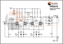
that is circuit of my PRE
i understand your circuit, what i want to know is if you match your tubes for transconductance between sections and between tubes?
or do you just stick them in like i do?
The best of my pre!
IM NOT understand WHAT DO YOU SAY!
That is the best of my Pre!
i understand your circuit, what i want to know is if you match your tubes for transconductance between sections and between tubes?
or do you just stick them in like i do?
IM NOT understand WHAT DO YOU SAY!
That is the best of my Pre!
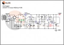
I use Hq supper shunt HQ regulate for My Pre
And use Salas CCS for it! I'm Thansk Salas very much!
And use Salas CCS for it! I'm Thansk Salas very much!
Attachments
Last edited:
Hi! all if you like My pre 818!
please make it follow all the value!
The cap 10nF, if you not like it, you can remove it!
The supply you can use SSHV shunt! it is good!
Thanks
please make it follow all the value!
The cap 10nF, if you not like it, you can remove it!
The supply you can use SSHV shunt! it is good!
Thanks
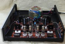
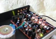
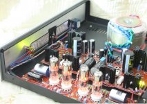
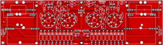
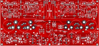
This circuit for PRE818, and some pictures, I have done it
Thanks
Thanks
Attachments

Last edited:
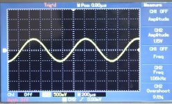
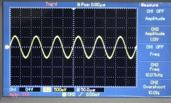
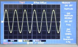
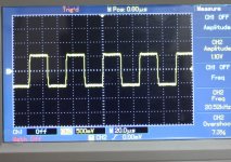
and some of my images measured Pre818
Attachments


- Status
- Not open for further replies.
- Home
- More Vendors...
- Quanghao Audio Design
- The best preamplifier