Hi All
This is a design I did in 5 years!
It has been many favorite friend. Especially in 2011 I have improved dramatically! To me this is my best pre tube using 6H30Pi or 6Dj8 ...
I opened the topic here, because this is the place to discuss all matters of Audio uses tube!
Sounds very realistic detail, balance!
Attachments
Last edited:
Hello Quanghao,
whats the bias and why is the gain so high for a linestage? I thought you said somewhere it was less than unity gain?
whats the bias and why is the gain so high for a linestage? I thought you said somewhere it was less than unity gain?
Miller effect? It would need to be driven from a low impedance source, otherwise some HF cut is likely - it could sound smooth (i.e. inaccurate).
Miller effect? It would need to be driven from a low impedance source, otherwise some HF cut is likely - it could sound smooth (i.e. inaccurate).
Presumably, it will have a level control, which will allow the sound to change spectral balance at different volume settings.
Actually tubes input capacitance is less than most semi-insulators especially if talking about something like FE86 or KT88.
However personally I would prefer mu-followers for triodes like 6N6P -30P, 6DJ8
However personally I would prefer mu-followers for triodes like 6N6P -30P, 6DJ8
Miller effect? It would need to be driven from a low impedance source, otherwise some HF cut is likely - it could sound smooth (i.e. inaccurate).
Yes!
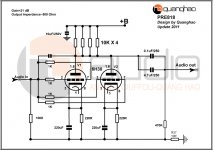
This cap Miller = 10pF!
Output impedance about 500R
Hello Quanghao,
whats the bias and why is the gain so high for a linestage? I thought you said somewhere it was less than unity gain?
+ B= 160V
One Tube = 17.5 mA
One channel need ~35mA
Yes!
This cap Miller = 10pF!
How do you arrive at that number? From the datasheet values, one would expect about 12-15 times higher.
How do you arrive at that number? From the datasheet values, one would expect about 12-15 times higher.
Hi!
By practical experience!
I practice many times and found that the best results!
OK, so no measurement or calculation, just assertion from the seller.
Using a more conventional engineering approach, one should expect 120-150pF, maybe somewhat more, depending on strays from wiring (which can be considerable with four paralleled sections) and how optimistic the datasheets are.
Using a more conventional engineering approach, one should expect 120-150pF, maybe somewhat more, depending on strays from wiring (which can be considerable with four paralleled sections) and how optimistic the datasheets are.
OK, so no measurement or calculation, just assertion from the seller.
Using a more conventional engineering approach, one should expect 120-150pF, maybe somewhat more, depending on strays from wiring (which can be considerable with four paralleled sections) and how optimistic the datasheets are.
Yes!
This design is not the same as datasheets, as you've seen before I like to use datasheets, each tube 6.30 40mA using bias, Pre almost like a power amplifier.
Sounds very, very hard and expensive electricity too!
you can use 120-150pF , if you like it! or not use the value or me!
By practical experience!
Curious: what is the 'practical experience' you have had that provided you with the 10pF number?
I can understand if you say, "well in my experience the input capacitance does not negatively affect the sound", it's another thing entirely to say your experience provided you with a number.
Does the OP mean that his anode-grid capacitor is 10pF? If so, that means Miller capacitance of around 500pF at the input, when the valve capacitance is included too. To get a -3dB point at 20kHz requires 16k source impedance, so volume pot must be less than 64k. A 50k pot would give -3dB at 25.5kHz at mid setting, and better at higher or lower volume.
Feasible, but I am not a great fan of circuits which significantly vary their frequency response with volume setting. This could, however, in the hands of a journalist or saleman be called a positive feature as the sound could come into 'focus' at certain settings, this demonstrating the 'fine discrimination' of the poorly designed equipment.
Feasible, but I am not a great fan of circuits which significantly vary their frequency response with volume setting. This could, however, in the hands of a journalist or saleman be called a positive feature as the sound could come into 'focus' at certain settings, this demonstrating the 'fine discrimination' of the poorly designed equipment.
You had to write my best preamp.
Miller is more of course. And of course the parallel path is not good for fidelity.
Miller is more of course. And of course the parallel path is not good for fidelity.
For 6N30P: Cgk=6.3pF, Cga = 6.0pF
Given circuit gain = 21 dB, A = 11.2
Miller capacitance: 11.2 x 6.0 pF = 67.2 pF (for one tube)
Input capacitance: Miller + Cgk + strays (say, 5 pF) = 78.5 pF (for one tube)
Total Cin for two tubes = 157 pF
Source inpedance = 47 k, ---> f(-3dB) = 21.5 kHz
Does anyone agree ?
Given circuit gain = 21 dB, A = 11.2
Miller capacitance: 11.2 x 6.0 pF = 67.2 pF (for one tube)
Input capacitance: Miller + Cgk + strays (say, 5 pF) = 78.5 pF (for one tube)
Total Cin for two tubes = 157 pF
Source inpedance = 47 k, ---> f(-3dB) = 21.5 kHz
Does anyone agree ?
Art, it appears that there are four sections in parallel, so minimum of 300pF by your calculations. My guess would be a bit higher because all of that wiring is likely to increase Cgp.
I'm still scratching my head about the 10pF.
I'm still scratching my head about the 10pF.
Don't forget the 10pF cap he added. He has four triodes in parallel. I used voltage gain of 30 (valve mu), as it didn't occur to me that he might be deliberately running them into a low anode load to get extra distortion. Anyway, we are still talking about 100's of pF so the line stage input C could exceed likely cable C.
The source impedance is likely to be lower than 47k. Even a bad source will have an impedance not much above a few k, and then a 100k volume pot will give a maximum source impedance just above 25k.
The source impedance is likely to be lower than 47k. Even a bad source will have an impedance not much above a few k, and then a 100k volume pot will give a maximum source impedance just above 25k.
For 6N30P: Cgk=6.3pF, Cga = 6.0pF
Given circuit gain = 21 dB, A = 11.2
Miller capacitance: 11.2 x 6.0 pF = 67.2 pF (for one tube)
Input capacitance: Miller + Cgk + strays (say, 5 pF) = 78.5 pF (for one tube)
Total Cin for two tubes = 157 pF
Source inpedance = 47 k, ---> f(-3dB) = 21.5 kHz
Does anyone agree ?
Almost !
You've just forgoten the "magical" deliberatly added 10pF that makes this preamp "the best" 🙄
Here is "The Better Preamplifier Of The Whole Know And Unknow Universe" :


Yves.
- Status
- Not open for further replies.
- Home
- More Vendors...
- Quanghao Audio Design
- The best preamplifier