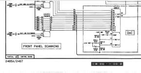
In order to save people the headache and the location of calibrations
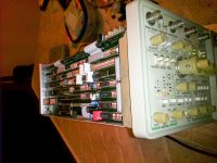
Photos from the process.
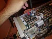
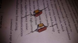
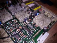
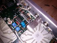
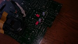
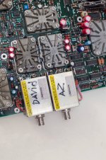
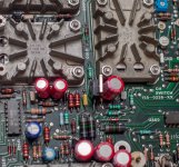
I also replaced the in the A5 borad
The 47UF capacitor to the bios ref voltage C2010
The original C2010 the ESR was Relatively high above 1.2 ohm
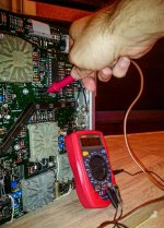
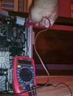
After the change
The reference voltage is very stable.
Anticlockwise
and clockwise
the ref v is 1.24v =2.48v
Photos from the process.
I also replaced the in the A5 borad
The 47UF capacitor to the bios ref voltage C2010
The original C2010 the ESR was Relatively high above 1.2 ohm
After the change
The reference voltage is very stable.
Anticlockwise
and clockwise
the ref v is 1.24v =2.48v
Attachments
-
 20934208_3735917719774_2375353440136333341_o.jpg180.6 KB · Views: 206
 -
 20934008_3735919079808_4436851212952890784_o.jpg372.1 KB · Views: 207
 -
 20933962_3735917999781_3863142940009050627_o.jpg415.7 KB · Views: 201
 -
 20934127_3735918679798_8474142007389729983_o.jpg453.1 KB · Views: 198
 -
 20934823_3735918839802_787992602838162634_o.jpg292.6 KB · Views: 188
 -
 20988137_3735918479793_1820797908584875384_o.jpg469.7 KB · Views: 99
 -
 20953027_3735919279813_1421564789791530516_n.jpg118.4 KB · Views: 88
 -
 20953192_3735919679823_6382989049689157728_n.jpg99.6 KB · Views: 99
 -
 20935152_3735919919829_239563454731000783_o.jpg274.6 KB · Views: 91
 -
 20988154_3735920119834_5747787940903589011_o.jpg243.5 KB · Views: 96
Last edited:
😎
Attachments
-
 21200745_3747712654640_8160962517359002368_o.jpg398.4 KB · Views: 85
 -
 21200733_3747706974498_9133374759046995453_o.jpg269 KB · Views: 84
 -
 21246296_3747712094626_5291584667120161262_o.jpg342.3 KB · Views: 90
 -
 21248470_3747079718817_7474458719261676269_o.jpg396.2 KB · Views: 90
 -
 21246622_3747703734417_4471647543394495835_o.jpg293.1 KB · Views: 99
 -
 21200514_3747706414484_3910330582019145641_o.jpg293 KB · Views: 98
 -
 21199777_3747065878471_4321578463940097350_o.jpg168.8 KB · Views: 98
😉
Attachments
-
 21316150_3749545300455_3267020456215115937_o.jpg360.8 KB · Views: 65
 -
 21316124_3749548140526_5796332109214623827_o.jpg196.5 KB · Views: 60
 -
 21273324_3749546060474_3659902971956570628_o.jpg251.3 KB · Views: 61
 -
 21273311_3749550380582_1712743219038570528_o.jpg172.6 KB · Views: 61
 -
 21273154_3749544020423_5360627634832296325_o.jpg301.5 KB · Views: 60
 -
 21273141_3749548540536_8627911324862845267_o.jpg207.9 KB · Views: 67
 -
 21272706_3749544820443_8804259531621239464_o.jpg303.6 KB · Views: 68
 -
 21248384_3749546900495_4744681160425866946_o.jpg281.5 KB · Views: 64
 -
 21200700_3749548740541_4366489500038512540_o.jpg253.7 KB · Views: 85
🙂
Attachments
-
 21272833_3749552500635_8781069635905812183_o.jpg429.4 KB · Views: 54
 -
 21427124_3749554220678_6133580920459087415_o.jpg440.1 KB · Views: 63
 -
 21368972_3749554900695_3454975019007907746_o.jpg260.7 KB · Views: 58
 -
 21368856_3749549860569_8992368644348023335_o.jpg335.2 KB · Views: 52
 -
 21368801_3749543820418_1126170980187748852_o.jpg287.3 KB · Views: 51
 -
 21367003_3749544620438_2014358678639642019_o.jpg250.7 KB · Views: 67
 -
 21273456_3749560340831_2495549672305583154_o.jpg158.7 KB · Views: 56
 -
 21319118_3749555980722_1805684350618058007_o.jpg266.6 KB · Views: 56
 -
 21316346_3749545860469_8387190979048390961_o.jpg311.4 KB · Views: 59
 -
 21316331_3749547940521_9173795359719505792_o.jpg203.5 KB · Views: 57
😛
Attachments
-
 21366879_3749590781592_1081815273933232208_o.jpg189.9 KB · Views: 69
 -
 21319018_3749591381607_7012153764653419471_o.jpg302.7 KB · Views: 54
 -
 21318963_3749590981597_651190458616186563_o.jpg259 KB · Views: 56
 -
 21316396_3749592261629_1156138071879836501_o.jpg251.1 KB · Views: 52
 -
 21316393_3749592061624_4968607018626859355_o.jpg264.7 KB · Views: 57
 -
 21273345_3749591141601_8941290361657418260_o.jpg287.6 KB · Views: 52
 -
 21273154_3749544020423_5360627634832296325_o.jpg206.6 KB · Views: 47
 -
 21272932_3749591581612_460426731968027797_o.jpg265.3 KB · Views: 63
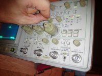
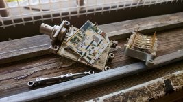
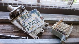
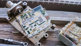
Now to the question
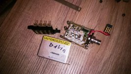
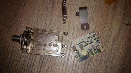
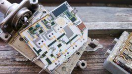
To all those interested in why I dismantled the printed circuit A1
I had a problem with the vertical scan I thought it was the attenuation
I ended up in the end
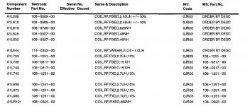
LR101 ( RF coil) burnt at first had a problem scanning, and Channel 2 stopped working.
This component resistor in parallel with coil 0.5UH
MARK 0325
108-0325-00
Can I create it
Something knows what the resistors value of LR101
After that I can wrap a coil on it until about 0.5UH ?
To all those interested in why I dismantled the printed circuit A1
I had a problem with the vertical scan I thought it was the attenuation
I ended up in the end
LR101 ( RF coil) burnt at first had a problem scanning, and Channel 2 stopped working.
This component resistor in parallel with coil 0.5UH
MARK 0325
108-0325-00
Can I create it
Something knows what the resistors value of LR101
After that I can wrap a coil on it until about 0.5UH ?
Attachments
Last edited:
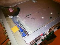
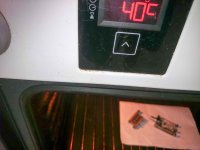
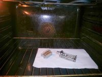
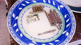
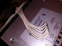
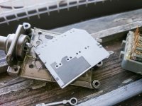
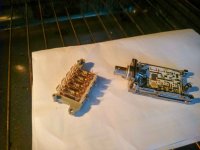
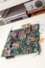
Clean water 😉
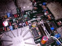
I always clean PCBs like that
At first with alcohol
After that with water and delicate soap Brush with a brush .
And then with distilled water.
Bake in the oven for about 40 degrees.
And finally a cleaner with alcohol
I always clean PCBs like that
At first with alcohol
After that with water and delicate soap Brush with a brush .
And then with distilled water.
Bake in the oven for about 40 degrees.
And finally a cleaner with alcohol
Attachments
-
 21316371_3747708934547_1858025161534475217_o.jpg248.7 KB · Views: 238
 -
 21273709_3747708054525_31323986233941462_o.jpg255.8 KB · Views: 234
 -
 21273656_3747708454535_8889123042497125137_o.jpg261.9 KB · Views: 228
 -
 21246602_3747710854595_1742608930180955640_o.jpg317.6 KB · Views: 241
 -
 21200448_3747712894646_8591754379171911175_o.jpg340 KB · Views: 244
Last edited:
I know but I took the riskI see bubbles?
This "Do not wash in water"?
At first I thought the problem with the unstable scan was that
attenuation
And at the end of the problem was not at
attenuation.
At least after that they were clean.
There was dirt in them that the gray was brown.
I have a much harder problem right now.
I need to create the coil resistors.
0325
0.5UH
I need to get a RF coil next week.
744762247A Wurth Electronics | Mouser Israel
Inductance: 470 nH
Tolerance: 5 % Maximum
DC Current: 420 mA
Maximum DC Resistance: 1.17 Ohms
Minimum Operating Temperature: - 40 C
Maximum Operating Temperature: + 125
C Product: RF Inductors Shielding: Unshielded Termination Style: SMD/SMT Package/Case: 1008 (2520 metric)
Length: 2.5 mm Width: 2 mm Height: 1.6 mm
Packaging: Reel Brand: Wurth Electronics
Case Code - in: 1008
Case Code - mm: 2520
Q Minimum: 45
Self Resonant Frequency: 480 MHz
Factory Pack Quantity: 2000
Test Frequency: 100 MHz
But I do not think it will work.
Because what I understood is an LR filter
If I knew the value of resistor
I could wrap a coil with resistor up to about 0.5UH
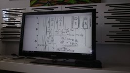
At least I try to make as many shots of all the printed circuits as possible
of the 2465
if someone has a problem in the future
Less will guess what to do
You do not know how much I looked for pictures of
attenuatior pcb
Last edited:
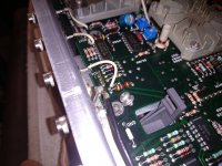
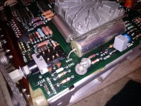
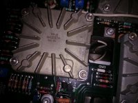
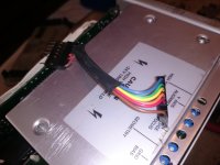
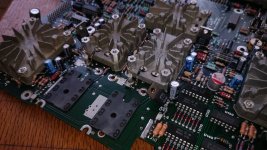
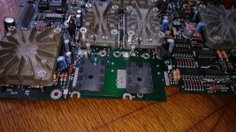
Referring to your 3rd pic in #66, what's that U-shaped thing in a small heat sink with three solder points, which is connected to this white wire emerging from the lower right corner?
Best regards!
Best regards!
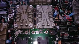
UD800 hibrid ic
UD800 hybrid ic heat sink
UD800 hybrid ic heat sink
Attachments
Last edited:
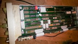
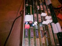
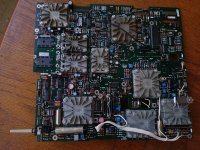
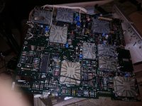
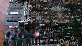
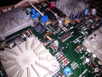
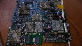
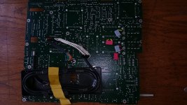
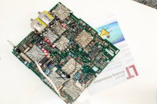
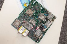
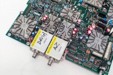
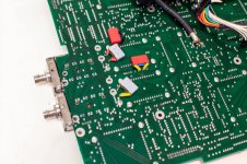
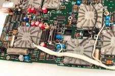
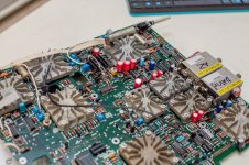
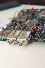
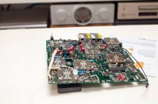
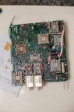
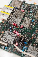
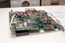
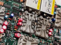
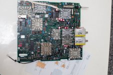
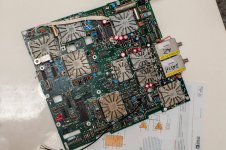
more photo fo the A1 pcb mod
Attachments
-
 21765498_3756405511956_8700616808414253426_o.jpg317.3 KB · Views: 82
 -
 21753016_3756406071970_8888958505282078700_o.jpg333.5 KB · Views: 74
 -
 21752806_3756402351877_2915071736991067776_o.jpg337.6 KB · Views: 65
 -
 21752592_3756402711886_8255100543619104096_o.jpg315.2 KB · Views: 62
 -
 21752556_3756403191898_5914624915236144148_o.jpg333.9 KB · Views: 76
 -
 21741055_3756407712011_2581202426376009748_o.jpg283 KB · Views: 72
 -
 21740963_3756403551907_5676325535173897642_o.jpg317.3 KB · Views: 83
 -
 21731040_3756407272000_908235968181349522_n.jpg95.8 KB · Views: 87
 -
 21728981_3756405191948_209666115694406852_o.jpg329.6 KB · Views: 117
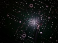
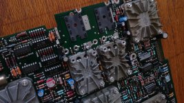
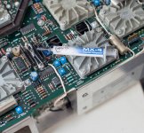
I finished the A1 board
I repositioned the LR107
Instead of burnt LR101
So LR101 is directly related to the LR201
To Pin 1 on
U100
U200
The LR107 I switched to TE's 470NH coil - SC30R47KT
I checked the resistance of LR101 / 201
108-0325
The resistance is about 0.4 ohm
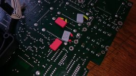
On the way I replaced most of the resistors in the printed circuit
To 0.1 percent accuracy.
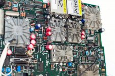
All electrolyte capacitors were replaced with electrolytic polymer capacitors.
47UF
10UF
220UF
100UF
Some of the 22NF ceramic capacitors
and the 100pF ceramic capacitors i replace to 1000pF 5000v NP0
Have been replaced to capacitors NP0 22nf 1000v
In addition to some of the ceramic capacitors
100 NF
100PF
470PF
I switched to film caps
of
wima
vishay 1837
Only remains put together
And hope that everything is fine
I repositioned the LR107
Instead of burnt LR101
So LR101 is directly related to the LR201
To Pin 1 on
U100
U200
The LR107 I switched to TE's 470NH coil - SC30R47KT
I checked the resistance of LR101 / 201
108-0325
The resistance is about 0.4 ohm
On the way I replaced most of the resistors in the printed circuit
To 0.1 percent accuracy.
All electrolyte capacitors were replaced with electrolytic polymer capacitors.
47UF
10UF
220UF
100UF
Some of the 22NF ceramic capacitors
and the 100pF ceramic capacitors i replace to 1000pF 5000v NP0
Have been replaced to capacitors NP0 22nf 1000v
In addition to some of the ceramic capacitors
100 NF
100PF
470PF
I switched to film caps
of
wima
vishay 1837
Only remains put together
And hope that everything is fine
Attachments
-
 21751328_3757809427053_6363723142565254096_n.jpg53.1 KB · Views: 64
 -
 21742968_3757809147046_9010466923497956125_n.jpg81 KB · Views: 61
 -
 21741008_3757806066969_7778828884639604236_o.jpg197 KB · Views: 63
 -
 21740537_3757810627083_590177570138879499_n.jpg100.9 KB · Views: 76
 -
 21731597_3757805826963_175202960680753550_o.jpg509.8 KB · Views: 77
 -
 21731110_3757812227123_810670729075932661_n.jpg118.8 KB · Views: 71
 -
 21728960_3757807106995_657239160888375625_o.jpg203.1 KB · Views: 69
 -
 21728919_3757806786987_1814850118975056483_o.jpg351.8 KB · Views: 70
 -
 21728885_3757810907090_2099495009023449201_o.jpg372.9 KB · Views: 77
 -
 21743688_3757811947116_5898905600700900863_o.jpg419.6 KB · Views: 68
Last edited:
my 3 tek
2445
2465
full reconstruction
About 600 photos you are welcome to see on my facebook
I have not been here for a long time
I am usually found in groups of tektronx
And measuring equipment
Page Not Found | Facebook
2445
2465
full reconstruction
About 600 photos you are welcome to see on my facebook
I have not been here for a long time
I am usually found in groups of tektronx
And measuring equipment
Page Not Found | Facebook
May replace the Y caps, while had a smoke on them (often culprit also seen on web). While today's power is 230V and a cap with 300V is required.
Hp
Hp
I would suggest 600V Y caps to ensure no early failures. if the cap is across the power line it is usually very conservatively rated BUT its pretty amazing what bad stuff can appear across the line. And while it may only be 100 uS long and less than once a year it could still blow things up.
- Status
- Not open for further replies.
- Home
- Design & Build
- Equipment & Tools
- The best gift I have ever received Tektronix 2465