Hi googlyone, interesting.
See my live measurements in combination with rather low-distortion OPS.
The level is much lower than the one you have just mentioned.
What I'm thinking - this front-end design is relatively low OLG.
As a result, having the amp gain 29db, the loop gain is only 35db - it's deliberately low, that's one of my design principle at this time.
If two amps with virtually the same front-end are showing so different distortion levels, than maybe the reason in the OPS distortion levels difference?
It would be interesting if you can measure the front-end standalone, with no OPS...
Cheers,
Valery
Attachments

I must say, to my untrained eyes, that the front end as drawn/built by Googlyone looks a bit different (more complex with additional parts) from the one by vzaichenko. Perhaps there are subtle differences? Most having to do with fact it was a mod from original circuit to take advantage of current drive approach.
I know that matching the input parts by Hfe (within 2%) on my VHex amp resulted in an amp with the best offset drift performance I have seen. 0mV initial setting and no more than 1mV offset after warmup and playing music. Very stable. Vzaichenko's circuit uses LEDs for the VAS bases though.
I know that matching the input parts by Hfe (within 2%) on my VHex amp resulted in an amp with the best offset drift performance I have seen. 0mV initial setting and no more than 1mV offset after warmup and playing music. Very stable. Vzaichenko's circuit uses LEDs for the VAS bases though.
Last edited:
The blameless amp used a cascode buffer, which I left in there. It should have no effect on the distortion.
In this application it really serves no purpose - and is really of use in a higher voltage design - but it does no harm either. This is clearly evident in the performance of the amplifier using the "blameless" topology.
The HFE of the transistors as measured on my completely random operating point multimeter was indeed within a few percent. I can't promise at what current though!
It is less about matching HFE though.
- The current required through N22 from post 40 at zero output needs to pull current through R30 to drive the VAS to zero output.
-> The current is a function of both the upper and lower constant current sources
-> And the resistances R3 and R4
-> And the differential pair CCS
A few percent error in matching of the current through the two sides of the differential pair (say 1% of 3mA) divided by the HFE, say 200, results in a base current difference of +/- 1.5E-7 Amps. Sounds small.
But the resistance seen from the base is 47k. but this results in a +/-7mV error in base voltages. Adds up quickly.
Without fine tuning, and because the differential pair does not use any current mirror, the error is a lot more than 1%. (I saw 200mV when I first turned the thing on!)
but that is really a side point - I think there are ways to get much better balance than tweaking resistors. Which I hate. I just want to get that distortion under control first!
To start this I will do three tests:
- hack one of the current mode boards back to a blameless type. The intent here being to demonstrate that shifting the VAS of this board and these parts back to a blameless type gets rid of the distortion.
-> If not, then I can hunt down and fix the gremlin
-> If it does, then I have learned something.
- Start putting it back together again into current mode - and see where things go flaky.
- Look at something, even if more complex, that is less likely to require the differential pair to throw itself out of balance - as after a glass of red, I am wondering if the drive into N22 itself is not unbalancing the differential pair enough to cause the distortion I am seeing.
For the best performance, you need to mane the collector current of N3 (as well as P7) equal to collector current of N22.
You can balance the LTP, using a trim pot in series with R11.
You can balance the LTP, using a trim pot in series with R11.
A possible experiment/test.
Compare the IM & THD between the output stage being multiple small transistors and a pair of equivalent "high power" transistors
Since this is a low power amp it ought to be pretty easy to find a complementary pair that has similar specs to the specs of the "multi-transistor". I'd be very curious to see real world tests and comparison.
_-_-bear
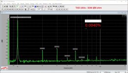
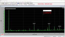
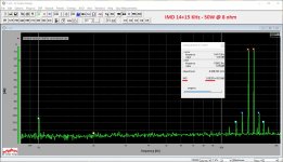
I managed to take the poorly performing current-driven-VAS amplifier and do "VAS surgery" on it, converting it back to a blameless architecture. Essentially identical to the initial amplifier.

The performance with no load and an 8R at about 3dB below clipping load is shown blow - noye this is the SAME board hacked back to blameless as pictured above:

Quite evidently everything on the board is working just fine - and it is absolutely an issue in the VAS drive that is at issue here.
Conclusions:
- OK the initial implementation was not finely tuned on the VAS drive / VAS currents.
- The initial Current Drive VAS version was reasonably balanced on the input differential pair.
- The simple one transistor implementation is probably not the sort of thing you would want to make without planning for a bunch of tuning. Indeed, I still don't know why the distortion was so utterly rubbish.
- I do need to go back and make the current drive work - even if just from curiosity.
- I do want to come up with an implementation that is no so dependent on tuning, twiddling pots etc - they are rubbish for production / repeatability.
Observations:
- One of the strengths of the blameless config is it is all managed inside a couple of feedback loops - global feedback and local in the case of current mirrors etc. It does what it does.
- I am going to try a hybrid was shown in an earlier post that I think will come a lot closer to a "no fiddling" current drive VAS without using a bucketload of devices.
- This will be an hour or two's "ratsnesting" of this board - but I think will be interesting to see.
Final thought:
- I am potty. OK, I was watching football with the wife while loading all those resistors and transistors, but damn... there are TOO many of them!!!
The performance with no load and an 8R at about 3dB below clipping load is shown blow - noye this is the SAME board hacked back to blameless as pictured above:
Quite evidently everything on the board is working just fine - and it is absolutely an issue in the VAS drive that is at issue here.
Conclusions:
- OK the initial implementation was not finely tuned on the VAS drive / VAS currents.
- The initial Current Drive VAS version was reasonably balanced on the input differential pair.
- The simple one transistor implementation is probably not the sort of thing you would want to make without planning for a bunch of tuning. Indeed, I still don't know why the distortion was so utterly rubbish.
- I do need to go back and make the current drive work - even if just from curiosity.
- I do want to come up with an implementation that is no so dependent on tuning, twiddling pots etc - they are rubbish for production / repeatability.
Observations:
- One of the strengths of the blameless config is it is all managed inside a couple of feedback loops - global feedback and local in the case of current mirrors etc. It does what it does.
- I am going to try a hybrid was shown in an earlier post that I think will come a lot closer to a "no fiddling" current drive VAS without using a bucketload of devices.
- This will be an hour or two's "ratsnesting" of this board - but I think will be interesting to see.
Final thought:
- I am potty. OK, I was watching football with the wife while loading all those resistors and transistors, but damn... there are TOO many of them!!!
- Status
- Not open for further replies.