Chris,
Is it fair to assume you are measuring the distortion across an 8 ohm resistor?
Do all the voltages and currents check out in the circuit?
Are you using the PCB from the article?
I'm sure we can figure this out. Maybe you can post some photos?
Is it fair to assume you are measuring the distortion across an 8 ohm resistor?
Do all the voltages and currents check out in the circuit?
Are you using the PCB from the article?
I'm sure we can figure this out. Maybe you can post some photos?
Excuse me Chris, you know, it is because my crappy English.
As I usually say, I'm not an EEE mind.
Still, for me the first suspects are the JFETs.
My biggest suck (actually one and only suck 🙂 ) with Pass amps was because of fake 2SJ74, when I was try to bring to life my SONY VFET amp.
These fakes matched well on IDSS, yet these were completly useless.
Well, Michael is here, so there can't be a problem.
I haven't build it yet, but I want to. 🙂
Crappy FETs would certainly cause a problem. I just don't have much familiarity with the fakes or how to identify them. If you PM me, I might have a pair lying around in a drawer somewhere 🙂
Dear Michael,
If you addressed your offer to me, it is quite generous.
Actually I have two matched pair for my next SONY VFET amp ordered third batch.
Momentarily (as usual) I don't have money, but if will be me, I would happy to buy some, for future projects.
Kind regards,
Gyuri
If you addressed your offer to me, it is quite generous.
Actually I have two matched pair for my next SONY VFET amp ordered third batch.
Momentarily (as usual) I don't have money, but if will be me, I would happy to buy some, for future projects.
Kind regards,
Gyuri
If you find yourself in need of a pair, I'm sure we can work something out.
I'll extend the same offer to Chris if it turns out he has fakes.
🙂
I'll extend the same offer to Chris if it turns out he has fakes.
🙂
Now I can't imagine that, an amplifier can be better than SONY VFET.
But I have to build more and more, this surely is an infectious disease here.
And I must have to build a circlotron amp, because it is so much a Yin and Yang thing. 😀
But I have to build more and more, this surely is an infectious disease here.
And I must have to build a circlotron amp, because it is so much a Yin and Yang thing. 😀
I find the Toshiba data sheet for the 2SJ74 completely ambiguous as to which leadout is the drain and which is the source.
The transistor is completely symmetric, so it doesn't matter as long as you
use the center pin as the Gate.
Hello Michael. Glad to find you here!
I think my measuring setup is OK. I'm using a Keithley 2015 THD multimeter. The + and - inputs are both floating with respect to ground. The lower limit on the distortion I can measure is effectively set by my Tenma audio signal generator, which is nominally about 0.05% distortion.
I'm driving your circlotron amplifier by means of an unbalanced to balanced preamp, based on the Balanced Zen Line Stage of Nelson Pass. If I measure the distortion across the balanced output of the line stage, I get a very low figure (essentially unmeasurable given my signal source). This reinforces my confidence that all is well with my measuring setup.
One other thing I have just tried is measuring the distortion on the balanced signal between the drains of the two 2SJ74 jfets. It is again very high, and almost identical to the figures I reported in my previous post.
I suppose this suggests that the 2SJ74 jfets are the likely culprit. It was several years ago now when I built the amplifier, and I can't now recall where I got them (I do remember it was not trivial to find them). So I don't know how to answer Gyuri's question about their provenance. There is nothing on them that specifically indicates either Toshiba or Linear Systems.
One other thing occurs to me. I find the Toshiba data sheet for the 2SJ74 completely ambiguous as to which leadout is the drain and which is the source. There is a side view with the three leads clearly numbered, but in it one cannot tell if the 2SJ74 is lying with its semicircular curved face upwards or downwards. There is also a end-on view, which would in principle be unambiguously clear, except that the leads are not explicitly numbered in the end-on view. Maybe, or maybe not, the numbering is assumed to be in the same order as in the adjacent side-view picture. Considering that they could so easily have made it unambiguous with a little more effort, it is rather frustrating that some uncertainty remains!
I understand that with some, but not all, jfets, the drain and the source are essentially interchangeable. I don't know whether this is the case with the 2SJ74.
So, in summary, I am pretty confident that my measurement setup is correctly reporting the distortion that is occurring. The finger of suspicion would seem to be pointing, I suppose, at the 2SJ74 driver stage. Maybe because I am using the "wrong make" of 2SJ74? Or, just possibly, might it be because of a wiring mistake with drain and source interchanged in the driver stage? The latter would easily be settled, if someone could tell me unambiguously which lead is drain and which is source on the 2SJ74.
Thanks for your help!
Chris
Edit: I've now found a Linear Systems datasheet for the 2SJ74, and they at least have an unambiguous indication of which lead is which. And I did in fact wire them up correctly, according to their identification of the leads.
If you post a clear picture of the topside and the front-text-side of the JFETs, I think I can tell you if they are the real thing or fakes.
Chris,
Is it fair to assume you are measuring the distortion across an 8 ohm resistor?
Do all the voltages and currents check out in the circuit?
Are you using the PCB from the article?
I'm sure we can figure this out. Maybe you can post some photos?
Yes, I measured across 8 ohms. All the voltages and currents looked good. There are actually some rather low-res photos in post #165 on this thread. They don't really reveal much, I'm afraid, and I'm not sure that high-res of the same views would really help much. Without substantial dismantling I don't think much behind-the-scenes detail is visible.
It is very kind of you to offer a pair of genuine 2SJ74s. I had actually just located a supplier on E-Bay, based in Sacremento, which seems on the face of it to be an honest outfit selling genuine Toshiba items for which they do a precision matching. So I took the plunge and shelled out $50 for a matched quad. (I know I really only need two matched pairs, but that is what they were offering.) I'll see whether that leads to any improvement, and then I'll report back here. If I'm still having problems perhaps I could take you up on your offer at that stage.
Thanks,
Chris
The transistor is completely symmetric, so it doesn't matter as long as you
use the center pin as the Gate.
Well, you know Papa, I trust you!
So I've measured IDSS of a 2SK170BL (I have enough of them).
I have got 10 mA.
Then I turned it 180, and measured the same.
Is it then true, when you put it in a curve tracer, then you get the same curves both direction?
Chris, you have said, you have bought ten in a batch.
Can you take some close photo from remaining ones?
Can you take some close photo from remaining ones?
If you post a clear picture of the topside and the front-text-side of the JFETs, I think I can tell you if they are the real thing or fakes.
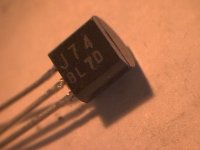
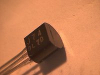
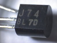
Here are a couple of shots of one of the others from the batch of 10 that I bought back when I was building the circlotron. The ones in the circlotron are the same as this one.
Edit: Just added a third pic with better lighting.
Chris
Attachments
Last edited:
Three questions:
Can you measure thickness between rounded and flat surfaces with a vernier caliper?
Can you easily remove labeling with some solvent? (eg. alcohol)
Is it painted, or etchwork?
I don't like that letters.
Can you measure thickness between rounded and flat surfaces with a vernier caliper?
Can you easily remove labeling with some solvent? (eg. alcohol)
Is it painted, or etchwork?
I don't like that letters.
Especially last two characters was suspicious to me, these are the cycle numbers.
Yet, I think these are genuines.
All of the genuine Toshiba ones (2SK170/2J74) I have, have a diameter almost exactly 3.9mm.
All of the fakes smaller in diameter, between 3.3-3.6mm.
Yet, I think these are genuines.
All of the genuine Toshiba ones (2SK170/2J74) I have, have a diameter almost exactly 3.9mm.
All of the fakes smaller in diameter, between 3.3-3.6mm.
Three questions:
Can you measure thickness between rounded and flat surfaces with a vernier caliper?
Can you easily remove labeling with some solvent? (eg. alcohol)
Is it painted, or etchwork?
I don't like that letters.
I don't have calipers. The best I can do just with a ruler is 4mm, maybe +/- 0.2mm.
The letters are etched (can be seen clearly in the third pic I posted).
Chris
Well, I think, these are really genuines.
Then, the question remains here, why there is a huge distortion?
I'm afraid, I'm too little for this.
Then, the question remains here, why there is a huge distortion?
I'm afraid, I'm too little for this.
The transistor is completely symmetric, so it doesn't matter as long as you
use the center pin as the Gate.
That's good to know. Thanks!
Chris
It seems unlikely as this is the first problem reported, but it is possible that the J74s were damaged by continuous testing at full power, which would push them just beyond their maximum rated Vds on peaks. If you replace them, I'd suggest limiting continuous testing to no more than 10W RMS output.
- Home
- Amplifiers
- Pass Labs
- The Amazing Fet Circlotron by Mike Rothacher