I'm planning to take balanced and unbalanced inputs for my Aleph 30.I want to switch between balanced and unbalanced with a toggle switch.Something like this http://www.penguinlovers.net/audio/aleph2_proj.html.Is there somebody who knows how I have to do this?And how I have to do the connection on the pcb-board and wich jumbers (opt)and the one near (in-) and do I need to install R6 normal or with wider footprint and do I need to install R0?
Perhaps a drawing would be nice.
Perhaps a drawing would be nice.
meanman1964 said:I'm planning to take balanced and unbalanced inputs for my Aleph 30.I want to switch between balanced and unbalanced with a toggle switch.Something like this http://www.penguinlovers.net/audio/aleph2_proj.html.Is there somebody who knows how I have to do this?And how I have to do the connection on the pcb-board and wich jumbers (opt)and the one near (in-) and do I need to install R6 normal or with wider footprint and do I need to install R0?
Perhaps a drawing would be nice.
if you understand how to connect XLR to pcb and RCA to pcb ,it's easy;
switch is there connected on XLR between - leg of signal and gnd .
just more convenient way instead installing jumper on XLR .
New A30
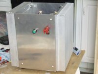
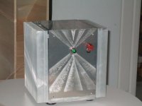
This is the a30 amp I built using P. Daniels boards. It is about 45 minutes running, using an ipod and one single test speaker switching channels. No hum noted, used the grounding scheme from the a30 voltage map[a lot of wires to star ground!] Heatsinks are warm but I can put my hand on them for abour 10 seconds max. Amp case is 12"X12"X10.5 deep.Heatsinks have a .50" base, seems about right. This was not an easy job to build, I cut the aluminum case panels and heatsink[it came in a 30" length] on my tablesaw. It works, that's a step forward. I would not like to pay myself for the time I took to build it. Still some panel fitting to do.
This is the a30 amp I built using P. Daniels boards. It is about 45 minutes running, using an ipod and one single test speaker switching channels. No hum noted, used the grounding scheme from the a30 voltage map[a lot of wires to star ground!] Heatsinks are warm but I can put my hand on them for abour 10 seconds max. Amp case is 12"X12"X10.5 deep.Heatsinks have a .50" base, seems about right. This was not an easy job to build, I cut the aluminum case panels and heatsink[it came in a 30" length] on my tablesaw. It works, that's a step forward. I would not like to pay myself for the time I took to build it. Still some panel fitting to do.
Attachments
pic.
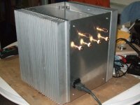
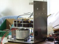
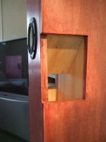
Back view
The power supply is the antek 400va-about 260 watts, 18vac+18vac[26 vdc] after rectifier. Used 2 35a 600v bridges, cap. is about 71,000uf/channel, crc filtered. This Antek is very quiet, can't hear any hum.
There is a top panel, but may want to keep an eye on it for a while. On power on, I was expecting the cl-60 inrush limiter to smoke, but it didn't. The 28volt power on light is tied to the top of the cap supply,I notice the power light fades out quick with power off.
just enjoying listening now, my 1st class A, I do have some 2a3 Bottlehead monoblcs. Can I say woo-woo?
Attachments
Aleph 30
For those who are interested in the A30, just some observations. This amp has a very quiet background, I have to put my ear up to the cone to hear any hum; 6" away nothing from my fe108ez, and this driver is quite efficient. Very tiny turn off pop-just so it can be heard. It is a good design and also the P. Daniel pcb works well. As stated in the a30 manual, you can change input leads and switch speaker cables with the amp on with no sound from the inputs and just a little static from the speaker leads; this is a very well behaved amp. Will form listening impressions later. 🙂
For those who are interested in the A30, just some observations. This amp has a very quiet background, I have to put my ear up to the cone to hear any hum; 6" away nothing from my fe108ez, and this driver is quite efficient. Very tiny turn off pop-just so it can be heard. It is a good design and also the P. Daniel pcb works well. As stated in the a30 manual, you can change input leads and switch speaker cables with the amp on with no sound from the inputs and just a little static from the speaker leads; this is a very well behaved amp. Will form listening impressions later. 🙂
As part of my goal to build a babelfish using Peter's boards, I found there was too much I didn't know to be able to do this comfortably. While digging through the babelfish schematic, I noticed that it was based on the original mini-A schematic.
I thought if I could first get a mini-A running on this board, I could then modify it into a babelfish.
I've gone through the (revised) mini-A schematic and using the BOM (and following the traces on Peter's boards), I've come up with the following resistor values and placement for building a mini-A on these boards. BEWARE however, that I have not completed mine, so it's possible there are mistakes - the part count on the mini is quite low, so it's not likely, but again not tested yet, so it's still a possibility
The formatting is a bit messed up, but there are 4 columns
Mini-A Resistor #
Mini-A resistor value
A30 resistor value
A30 resistor #
Input Section Mini-A Mini-A value A30 value A30
R3 10k 10k R3
R6 68.1k 68.1k R6
R8 ? R8
R4 100k 100k R4
R5 68.1k 68.1k R5
R2 10k 10k R2
R9 221 221 R9
R10 221 221 R10
R14 392 392 R14
Main Section R4 221 221 R11
R5 221 221 R5
R7 2k 4.75k R13
R8 10k 100k R7 * R7 is used due to difference in layout
R9 750 1.5k R17
R10 750 1.5k R18
R11 47.5k 47.5k R19
R12 750 820 R21
R13 100 392 R16
R14 221 221 R30
R15 1k 1k R20
R16 221 221 R33
R17 221 221 R15
R18 0.47 0.47 R36
R19 0.47 0.47 R39
R20 0.47 0.47 R23
R21 0.47 0.47 R26
The balanced-input mini-a looks like it's got the input section taken straight from the A30, so you end up with duplicated resistor numbers - that's what the different sections are for - to help clear this up.
It looks like there are only 5 or 6 changes R9/R17, R10/R18, R12/R21, R13/R16 (and R7 from A30 used in place of R8 on mini schematic since this looks like a minor variation between the 2)
As I don't know what these resistors do, I suspect they lower the current going to the output fets since we only use 2 instead of 6 in the mini.
Anyway, if I'm completely wrong, please feel free to flame away

I'm just another pilgrim trying to make the journey to the land of beautiful music
P.S. I did struggle for a while to find the corresponding resistor to R17 (R15 on the A30) and finally found that the output fets can only be used in Q8/Q11 due to the extra connection under the board where it's printed 'Q11' - no other output fets have this extra connection. 😉
I thought if I could first get a mini-A running on this board, I could then modify it into a babelfish.
I've gone through the (revised) mini-A schematic and using the BOM (and following the traces on Peter's boards), I've come up with the following resistor values and placement for building a mini-A on these boards. BEWARE however, that I have not completed mine, so it's possible there are mistakes - the part count on the mini is quite low, so it's not likely, but again not tested yet, so it's still a possibility
The formatting is a bit messed up, but there are 4 columns
Mini-A Resistor #
Mini-A resistor value
A30 resistor value
A30 resistor #
Input Section Mini-A Mini-A value A30 value A30
R3 10k 10k R3
R6 68.1k 68.1k R6
R8 ? R8
R4 100k 100k R4
R5 68.1k 68.1k R5
R2 10k 10k R2
R9 221 221 R9
R10 221 221 R10
R14 392 392 R14
Main Section R4 221 221 R11
R5 221 221 R5
R7 2k 4.75k R13
R8 10k 100k R7 * R7 is used due to difference in layout
R9 750 1.5k R17
R10 750 1.5k R18
R11 47.5k 47.5k R19
R12 750 820 R21
R13 100 392 R16
R14 221 221 R30
R15 1k 1k R20
R16 221 221 R33
R17 221 221 R15
R18 0.47 0.47 R36
R19 0.47 0.47 R39
R20 0.47 0.47 R23
R21 0.47 0.47 R26
The balanced-input mini-a looks like it's got the input section taken straight from the A30, so you end up with duplicated resistor numbers - that's what the different sections are for - to help clear this up.
It looks like there are only 5 or 6 changes R9/R17, R10/R18, R12/R21, R13/R16 (and R7 from A30 used in place of R8 on mini schematic since this looks like a minor variation between the 2)
As I don't know what these resistors do, I suspect they lower the current going to the output fets since we only use 2 instead of 6 in the mini.
Anyway, if I'm completely wrong, please feel free to flame away
I'm just another pilgrim trying to make the journey to the land of beautiful music
P.S. I did struggle for a while to find the corresponding resistor to R17 (R15 on the A30) and finally found that the output fets can only be used in Q8/Q11 due to the extra connection under the board where it's printed 'Q11' - no other output fets have this extra connection. 😉
I already found a mistake - in the main board section R5 corresponds to R12 on the board, sorry about that
twitchie said:As part of my goal to build a babelfish using Peter's boards...
I noticed quite a few people try to do that. If there is enough interest, I can convert the A30 layout to fit Bablefish circuit and offer completely new boards.
bias and dc offset
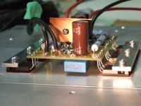
Can't well enough alone. The amp was great with nice sound stage depth, but I wanted more. So I upped the bias resistors from 47.5k to 68k. my heatsink temp went from 52* to 57*. This I didn't like. The sound took on a harder edge, like an ab amp. 47.5k is what I like. Balanced the offsets to about12mv; this I did by adding 12m ohm resistor to r8. The pdf. a30 voltage map Zen Mod provided explains this.
This amp has a full sound with good volume and punch. My speaks are the Alto double horn[my own build], about 3 ohms-fe108ez+8"mcm,like the hm "saxaphon"🙂
Attachments
Peter Daniel said:Well, here you are, problem solved.
I know that you can make them cheaper ,from multiple reasons;
depending what DIYa boyz want , choice can be their's 😀
I wasn't actually aware that those boards were available, in that case I don't want to interfere.
I may try to convert those A30 boards into Aleph X, maybe? 😎
I may try to convert those A30 boards into Aleph X, maybe? 😎
Peter Daniel said:I wasn't actually aware that those boards were available, in that case I don't want to interfere.
only with whom you (we) can interfere is Papa himself 😉
but -as he is who is.....................
I may try to convert those A30 boards into Aleph X, maybe? 😎
Babelfish X pcbs are on their way soon;
but-same conclusion as for previous one ..........name of the game is that DIYa boyz can have that pcbs as fast and as cheap as we can.
it really doesn't matter where some beer money is spent- in your or mine or anyone else's workshop 😉
- Status
- Not open for further replies.
- Home
- Amplifiers
- Pass Labs
- The Aleph30 PCB layout