Broek
No secrets here, joseph...
ststone has a live, he works and YES he has a computer @ home
En als je over een hek springt kan er een naad knappen, Willem O Duis
Its Nappa Valley for me (ik ga slapen)
No secrets here, joseph...
ststone has a live, he works and YES he has a computer @ home
En als je over een hek springt kan er een naad knappen, Willem O Duis
Its Nappa Valley for me (ik ga slapen)
Aleph & energy...
OK, I'll join you, and help with the death of universe....
Just need an electrician to rewire my house, to get a separate fuse for my amps!
It's just the day when you get billed from your energy-company, you start thinking of more efficient amps.
As I already have 1 x 2x250W + 1 x 2x150W Class A amps, plus more "colder" amps...and building the Aleph 2....
BTW, days are short, but not dark here. And, yes, they are cold!
ArneK
NORWAY
🙂
Cobra2, mr. Pass has this line in his documentation
So its all good.
Later, the sun will cool to a white dwarf, and after that the universe will experience heat death
So its all good.
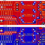
Any opinions on crosshatched ground planes? I noticed that Wayne used one for the Pearl phono layout. Is there any advantage to this over a solid ground plane?
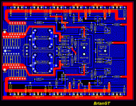
Here is a picture. I am finishing up my next version of my Aleph-X pcb with 3 devices per bank, all that I need to add is the components for Fred's CCS (making room for both).
BTW: the spacings on my board layout allow for 3 - 22.5mm caps per input, 2 - 27.5 caps per input or 1 - 37.5mm cap per input. There is a ground pad near the negative, for use for single ended versions to tie the input to.
--
Brian
Attachments
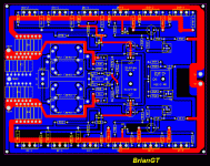
Here is a picture of my next layout. I did this one using Interactive Routing from a schematic in Protel DXP. I removed the top level ground plane, so that all traces could be shown. I am in the process of adding Fred's CCS on the right side after the regular CCS, as to allow for the option to choose.
This should make for quite a scalable pcb. If you want a lower powered version, just populate one of each bank, but for scaling up the power, 3 per bank should work rather well.
Any suggestions for improvements on the layout. The only drawback that I see is the large size of the board (6" x 8"), but I can deal with this. Unlike my first layout, all the devices can be mounted directly to the pcb (a little loss in symmetry, but well worth the convience).
EDIT: I realized that I forgot mounting holes and pads to tie the power to, and I am adding them now.
--
Brian
Attachments
Beautiful artwork, Brian. What's to keep you from making the board even larger in width and allowing for 12 power transistors per bank, 24 in all?
crosshatched ground planes...
They can be used to reduce amount of copper consumed in manufacturing, so in cost sensetive situations, they can save a few pennies. They are also lighter weight than solid ground planes, if that's a factor in the design, but in most cases it's not. Thermal conductivity and dissipation properties (think component heatsinking) are different too. All this for the small price of slightly reduced ground plane conductivity, which doesn't usually affect performance much, if at all. I think crosshatched ground planes can also help prevent board warpage due to the different thermal expansion coefficients of copper and FR4 substrate... probably a factor only in large boards, but to be honest, I've seen large through-hole components jammed into too-small holes cause far more severe board warpage problems.
These are all minor effects anyway, so in the end, I think it boils down to the designers sense of aesthetic. Some think they look nifty, but I personally prefer solid groundplanes simply because they have a higher conductivity (slightly), and I don't like the crosshatched look...
Oh yeah, and then there's the possibility of slightly reduced capacitance to ground...
Not to dis your work or anything (which is truly excellent!), but I feel that ground planes belong mainly in digital or mixed-signal circuitry, and some analogue circuits which involve very small voltages, high impedances, or require extremely low noise. I think in the power amplifier realm, a well implemented star-ground arrangement will usually outperform a ground plane. Once in a while, you'll find an area of the ciruit which benefits from the shielding provided by a ground plane or guard traces.
Not to dis your work or anything (which is truly excellent!), but I feel that ground planes belong mainly in digital or mixed-signal circuitry, and some analogue circuits which involve very small voltages, high impedances, or require extremely low noise. I think in the power amplifier realm, a well implemented star-ground arrangement will usually outperform a ground plane. Once in a while, you'll find an area of the ciruit which benefits from the shielding provided by a ground plane or guard traces.
carpenter said:Beautiful artwork, Brian. What's to keep you from making the board even larger in width and allowing for 12 power transistors per bank, 24 in all?
Absolutely nothing : ) It actually would be quite easy to do. By using a schematic, it makes all the nets for you, so all you have to do is place the components and use the interactive routing.
If you made it 12 per bank... that would be 24 per side and 48 overall. This would be quite a large pcb.
One of the reasons that I like 3 devices per bank, is that I have 2 sets of 12 matched IRFP240s here that I had from my Aleph 2 that I pushed to the side that I will use for my next Aleph-X. (my one now that I am building uses 8 per channel: http://brian.darg.net/aleph-x/aap )
--
Brian
hifiZen said:crosshatched ground planes...
I also like the look of solid ground planes, and the XA seems to use solid ground planes, so I will keep to this for now.
I added the mounting holes and power supply connections. Did I miss anything else? I am looking into also putting Fred's CCS on the board now.
--
Brian
Attachments
wuffwaff said:URSV,
you won´t find a 600VA transformer with 15 or 18v secondaries so easy.
But thats´s not a problem cause you can have them made at order for a few euros more.
william
UrSv said:Oh, that's why. I thought several suppliers had 12, 15, 18 V as standard outputs to fairly high ratings. At least the Swedish popular Toroid does for 500 VA and it is kind of "default" here.
http://www.elfa.se/elfa/produkter/se/18/185981.htm
Sorry to hear that. Obviously there's nothing wrong with custom transformers.
/UrSv
Transformer tip for Europeans?:
Reichelt has 12, 15 and 18 V at 330, 500 and even 800 VA. Prices are cheap at EUR 39 for 500 VA and EUR 56 for 800 VA.
Good Aleph-X choice?
/UrSv
Brian
more space for mounting holes would be nice, adding an extra mo in the dead center for stability would be even nicer. I have some concerns about the way you did the grounds. It maybe nothing but if it buzzes when you turn it on I may suggest some way to rework the grounds.
more space for mounting holes would be nice, adding an extra mo in the dead center for stability would be even nicer. I have some concerns about the way you did the grounds. It maybe nothing but if it buzzes when you turn it on I may suggest some way to rework the grounds.
Actually, Brian:
A tip for you: Move as many traces as possible to the bottom layer so that the top layer ground plane has the fewest breaks possible. In some cases where you have a single trace on the top layer going from pad to pad, you can improve this by running as much of the trace as possible on the bottom layer, and using vias to jump to the top layer where you need to cross over another trace. The goal is to provide the greatest uninterrupted ground plane area possible on the top side. Ideally, the ground plane has no holes, slots or anything... it would be one continuous solid sheet.
You can also insert plenty of vias between the top and bottom ground planes to connect the two sides, especially around areas where there is a discontinuity on one side. The best location for vias is along edges of the plane polygons, and possibly a sprinkling through large unbroken areas. Try to make one side of mostly traces, and the other side primarily unbroken ground plane.
Oh yes, and you should give some consideration to ground return current paths... note that high frequency currents tend to follow back along the trace carrying the reciprocal current (think transmission lines here). At DC and low frequencies, the ground return current will take the shortest path from load (the point where it's dumped to ground) back to source (usually the power supply ground connection point). For most audio frequency work, the return currents will take a fairly direct route through a pretty wide area of copper. Removing obstacles from the ground return current paths can help optimise the board. In addition, be careful to locate small-signal circuit ground points (especially those which are sensitive to a precise ground potential) away from high current ground return paths.
did i understand it right?
Hi,
to increase wattage of aleph x it is only to multiple output transistors? nothing else?
Whats with increasing power supply voltage?
thank you,
Ralf
Hi,
to increase wattage of aleph x it is only to multiple output transistors? nothing else?
Whats with increasing power supply voltage?
thank you,
Ralf
To increase power output (into the same load), you'll need to increase the number of devices, the supply voltage, the bias current, the closed loop voltage gain and the trigger point of the protection circuit (if you use it).
It seems every one wants more power. Not me. 30 to 50 watts is plenty.
Can the board work for lower power?
How many mosfets would be needed?
And I guess all the same adjustments for adding power would be needed for less power output?. How would these be calculated?
Thanks in advance.
Can the board work for lower power?
How many mosfets would be needed?
And I guess all the same adjustments for adding power would be needed for less power output?. How would these be calculated?
Thanks in advance.
- Home
- Amplifiers
- Pass Labs
- The Aleph-X


