I was tempted to rename Penultimate Zen as
"Resurrection of Zen", but I resisted.
It is bad enough that I named the Zen amplifier as a
tease to a reader who wrote into Audio Amateur
referring to an idea of mine as "goofy" and referring
to me sarcastically as "Zen Master Pass".
😉
"Resurrection of Zen", but I resisted.
It is bad enough that I named the Zen amplifier as a
tease to a reader who wrote into Audio Amateur
referring to an idea of mine as "goofy" and referring
to me sarcastically as "Zen Master Pass".
😉
Here I thought the ZEN amps were named after " Zen and the Art of Motorcycle Maintenance".
But (I think) since the ZEN articles in TAA, I have seen Zen tube amps, Zen cables, Zen capacitors, Zen speakers, and Zen headphone amps. What's next, An audio company name Zen?
😎
But (I think) since the ZEN articles in TAA, I have seen Zen tube amps, Zen cables, Zen capacitors, Zen speakers, and Zen headphone amps. What's next, An audio company name Zen?
😎
Of course the other justification is the koan,
"What is the sound of one transistor clapping?"
😉
"What is the sound of one transistor clapping?"
😉
Yesterday, I finished the first channel of my Aleph-X. Started testing and listening to this channel today. I am stunned.
I used the Grey's circuit as a starting point. Struggeld for weeks with this and the simulator. Did some very small modifications. Included Ian's resistors. DC stability is perfect. Details will follow soon.
Grey, Ian and of course Nelson, thanks again for sharing this.
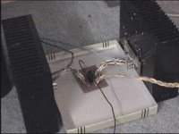
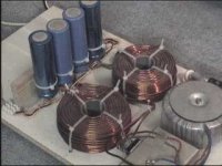
And this is what the real prototype looks like. (Sorry for the quality of the picture).
I used the Grey's circuit as a starting point. Struggeld for weeks with this and the simulator. Did some very small modifications. Included Ian's resistors. DC stability is perfect. Details will follow soon.
Grey, Ian and of course Nelson, thanks again for sharing this.
And this is what the real prototype looks like. (Sorry for the quality of the picture).
Attachments
Second channel will be ready in two or three weeks.
Yes, I have an ALEPH 3. So I will be able to compare.
Yes, I have an ALEPH 3. So I will be able to compare.
I'm little surprised that nobody (besides Mr. Pass, of course) came out with working prototype yet.😉
If it wasn't for Aleph5 and CD project I would've been done by now. BTW, can it operate with a single ended source and what are the consequences?
If it wasn't for Aleph5 and CD project I would've been done by now. BTW, can it operate with a single ended source and what are the consequences?
For best operation with single-ended source, the input
diff pair must see high impedance on their Source pins,
which you achieve by active current sourcing them and
not having resistors wandering off to ground and such.
diff pair must see high impedance on their Source pins,
which you achieve by active current sourcing them and
not having resistors wandering off to ground and such.
Nelson Pass said:...and not having resistors wandering off to ground and such.
Does this also include DC offset trim resistors from sources to output?😉
Did anyone ever determine what the best value is for the resistors from output to the node at the current source drain/differential pair sources connection? I somehow can't seem to find it by going back through the thread (could be that it's 23 pages long already!)
Rtirion,
Will you be providing the schematics your design was built with? I would like to see what actually worked, and how it was done.
Steve
Rtirion,
Will you be providing the schematics your design was built with? I would like to see what actually worked, and how it was done.
Steve
I tried a couple of value's. 10k was the first and least effective.
Used 4,7k and now 1k which I like best.
Today I did a test with an unbalanced input. Works fine, but I like the balanced input better.
Full schematic will be posted end of this week.
Used 4,7k and now 1k which I like best.
Today I did a test with an unbalanced input. Works fine, but I like the balanced input better.
Full schematic will be posted end of this week.
The lower the resistance, the more effective the control
over absolute DC, but then you start depending more
on the common-mode output cancellation to get better
input common mode rejection. I feel it is probably better
to go to higher resistance and use output resistance to
ground to additionally stabilize the absolute DC.
Remember also, the absolute DC offset figure is not
particularly important until it gets so large that it cuts into
the maximum power rating, so a volt or so won't hurt
anything if your inputs are capacitively coupled.
I recommend capacitive input coupling for this circuit
unless you can be assured of equal DC impedance
sourcing both inputs, otherwise you get thumps and
higher differential DC offset.
Of course, I am happy to sit there all night with my
voltmeter and screwdriver, adjusting the offset between
tunes just to avoid a capacitor. 🙂
- Home
- Amplifiers
- Pass Labs
- The Aleph-X