They aren't absolutely necessary but help to keep the ripple down without the need of too much capacitance.
They also provide a good way to lower your supply rails a bit, if necessary.
Since I need every fraction of volt that my trafo outputs I don't use them.
Cheers
Andrea
They also provide a good way to lower your supply rails a bit, if necessary.
Since I need every fraction of volt that my trafo outputs I don't use them.
Cheers
Andrea
Andy,
I'm using 4 36,000mF caps in the power supply per channel for + and -. Is that enough capacitance? I have one 12.6 volt trans per channel. I don't want to lose anymore voltage either.
thanks,
Vince
I'm using 4 36,000mF caps in the power supply per channel for + and -. Is that enough capacitance? I have one 12.6 volt trans per channel. I don't want to lose anymore voltage either.
thanks,
Vince
Some might say "yes", some might not.
It all depends on the ripple level you find acceptable and on the current requested from the power supply.
Schottky diodes also help, 'cause they are fast and have lower dropout than the others.
In my setup I use 2x300 VA 12V trafos and 3x39mF per rail (6 total) for each channel.
Total bias is about 5A and the ripple is, if I remember well, a few hundreds of mV pk-pk.
No hum problems or whatsoever.
Cheers
Andrea
Any Suggestions ?
Hello everyone ! Yap, just registered. Wish I have time playing with this Aleph-X thing. My day-time job has been killing me for the pass few years.
The attached circuit is my concept. It took on Mr. Pass’s “Less is More” philosophy. Based on the voltage swing and ASSUMMED load, the output pumps proportional current into the load. I like to hear opinions from some of the analog experts on this board, specially Mr. Pass himself if this concept can be incorporated into the Aleph-X somehow.
What are disadvantages ? (The average load has to be known for current pump scaling)
(Actually, I built the prototype 2 years ago. The thing still sounds great today – with the exception of light bottom which is a trait of most none feedback topology. Someday, (when I have time), I will build an Aleph to compare the 2.)
Attachments
In general, mixing gain devices seems to yield circuits that emphasize the worst of what each device has to offer. The same thing happens when you put tubes and solid state together in the same circuit. Looks good on paper, but it doesn't pan out in the real world.
Also, the MOSFETs and bipolars are going to behave differently, themally, and bias is going to be problematical.
That said, it certainly looks as though it should work. I'm assuming that this is more of a conceptual diagram, as I don't see how you're handling bias or DC offset.
Possibilities:
--Consider a split load phase splitter in place of the second and third MOSFETs. Getting the output balanced (and output stage biased) shouldn't be any more difficult than it is in your design. That would simplify things a bit.
--Use MOSFETs in place of the bipolar outputs, or bipolars instead of the MOSFETs.
I don't see that the circuit will be easily "Alephed" but it wouldn't be difficult to "X" it. Just turn the first stage into a differential and run the feedback from right to left and vice versa. Of course, then you'd no longer have a zero feedback design, but that's the nature of X.
Grey
Thanks for the inputs. Hopefully someone will have great ideas.
1) “In general, mixing gain devices seems to yield circuits that emphasize the worst of what each device has to offer. The same thing happens when you put tubes and solid state together in the same circuit.”
I respect your opinion and/or experience, but don’t necessary agree with it.
2) “Looks good on paper, but it doesn't pan out in the real world.”
I built the prototype 2 years ago and have been listening everyday – through the 1 Ohm Apogee Scintilla.
3) ”Also, the MOSFETs and bipolars are going to behave differently, themally, and bias is going to be problematical. That said, it certainly looks as though it should work. I'm assuming that this is more of a conceptual diagram, as I don't see how you're handling bias or DC offset.”
Positive and negative thermal coefficient, I see what you mean. But, this thing is stable. The Bipolars try hard but the FETs wouldn’t let them. Heatsink temp is up to 65, but only wandering around a few hundreds mV DC.
I apologize for not having the details - I didn’t draw out the current source on the first stage. With a POT on said current source, I was able to fix the 2nd stage’s drain a few volts above the outputs’ sources. That knocks off your DC offset.
“Possibilities:
--Consider a split load phase splitter in place of the second and third MOSFETs. Getting the output balanced (and output stage biased) shouldn't be any more difficult than it is in your design. That would simplify things a bit.
--Use MOSFETs in place of the bipolar outputs, or bipolars instead of the MOSFETs.
I don't see that the circuit will be easily "Alephed" but it wouldn't be difficult to "X" it. Just turn the first stage into a differential and run the feedback from right to left and vice versa. Of course, then you'd no longer have a zero feedback design, but that's the nature of X”
Yap, it was a long shot. I wouldn’t be surprise if it hurts rather than aid Mr. Pass' SuperSymetry benefits. I am not so sure on Mr. Pass’ output current source thought. (Is it chicken or the egg first).
FYI, there’s good reason I mixed the 2 at the output. FET is for easy driving. Bipolar (not just any Bipolar – look at the device’s Beta between 25 and 100 degrees when you run them at a few amps each, perfect for the job) for whole purpose of the topology – proportional current pump into the load driven by voltage swing !
It’s great to explore ideas !
TTH
BTW, (Mr. Pass) does your Patent cover Feed Forward Active Current Source too ? How’s about FFAX (Feed Forward Aleph X)
😀 😀 😀

If that's a constant current source off the input Source,
I don't see how you're going to get any gain.
I don't see how you're going to get any gain.
I tried to follow what Grollins told me to take some time, read the schematic of alephx, to find out how this amp works.
I tried to simulate by applying non-balanced input to this amp. So the + input is fed by signal, but the - input is grounded (so there is 10K//68k to ground).
With this kind of input, is the alephx has the same gain for left and right aleph? For me it seems that the left aleph has less output magnitude from the right aleph (absolute voltage to ground), if this alephx is fed by non-balanced input.
Also, with 10k, 100k, 68k to inputs, what is the formula of total gain of this amp? (I wanted to use different gain factor, but cannot figure the gain formula for alephx).
Thank you Mr. Pass. After a few years, I'm getting rusty at what I came up with (original circuit's in my storage). It should be the current source at the + rail, resistors on Drain and Source.
Keeping things the same concept which I like, any suggestions for improving it, specially the 2.5 stage drives the output current source at the - rail.
Keeping things the same concept which I like, any suggestions for improving it, specially the 2.5 stage drives the output current source at the - rail.
XA-AX layout
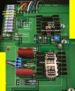
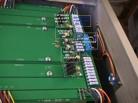
Following Nelssons advice ragardind the simetry of the layout for AX or XA and as a greate learning proces (I can see those shematics with my eyes closed-I don`t understand them unfortunatly) I tried to compare original PCB layout of 200XA with Gray`s shematic an Aleph shematics. I must say that I faled at input arangement allready, trying to implement varius ax shematics on the original layout (couse of my lack of electronics knowledge ofcourse).
Anyway I feel that does make sence to try to determine at least the positions of the basic circuitrys (out + -, ccs, diff pair, biass circuit, ...) on the board and try to implemente that to the PCB layout one will use for his DIY project.
Here are two pics. Nelsson kindly send on the forum, where I tryied to found out, what is going on on the board in general therms using Grays, Ritrion`s, Cheff`s and Nelsson`s Aleph shematics. I`d just like to know if I made any big mistakes by detemineing those sections or did I interchange any of them (like Q4 and Q3 for example).
thank`s
pic.1
Attachments
What happens if we simply put a current mirror before the 392 resistors? Will it eliminate the DC offset problem, or it will make the alephx not working at all?
TTH,
I'm not quite sure I understand when you say that the front end is loaded by a current source and that there are resistors at the Source and Drain. You're using a current source and a load resistor off of the Drain?
All the suggestions involve changing your circuit. Since you want to keep it the same, I'm not sure what else to suggest. If it works to your satisfaction and you like the sound of it, then don't change it.
marijan,
My schematic isn't necessarily going to be the same as Nelson's circuit. Trying to use it in an attempt to reverse-engineer the commercial XA product is likely to require a lot of ethanol and a high tolerance for frustration.
lumanauw,
Current mirrors will not do anthing to solve the DC offset problem. They may also lead to difficulties in biasing the circuit.
Grey
Thank`s Gray, I was just trying to follow Nelssons recomandation regarding mehanical layout of the boards (tip some where in the thread) All I tried was to understand where the sub circuits of the whole picture are located on the board to claryfie my confusion, and use simmilar positions when designeing my own boards by your shematic. I`m certanly not able and I`m not trying to backeng. the Nelssons circuit. I could have all the tolerance and time of this world.
Talking about confusion. Aleph2 when separated boards are used like I did (Marks, Wayns boards), have 7 comon (conecting) points to the main board. (drive, sense, gate - pos and neg chanal, and comon outpot point) .
One main board, two outp. boards 2x6 MFETS that`s Aleph 2 one monoblock.
AX or XA supouse to use one aleph monoblock (otput section) per side, so two for one XA chanal (monoblock).
There is 8 x 7 !! wire bus conections on the XA200 pics. Four of them certanly are seperated outp. boards conections (+S,+D,+V,0,-V,-D,-S) caried down there to other side of the board which create 4 aditional conect. Looking the shematics of Alephs and all AX`s - I yust dont get it. Like there are 4 Aleph monoblocs in one XA200 monoblock???.
I`m realy sory to bother anyone with this kind of questions, and I`m not expecting an answer or explanation, but if Nelsson was so kind to ofer an inlook I tried to understand the basic points of mecanical layout.
rgds
marijan
Mechanical layout is not such a big deal. Use common sense.
Use short wires.
Use fat wires on output stage power leads. Thin elsewhere is ok.
Don't put the input stage on top of the power transformer.
Keep the transformer as far away as possible/practical.
Tie all your dirty power supply grounds in one place, all your
clean signal sounds in one place, and run a wire between them.
Avoid ground loops.
Separate isolated power supplies for each channel is best.
There's other bits of wisdom, but you get the idea.
😎
Inverting X?
After reading the whole page of Aleph-X (168 pages), it is clear that X configuration is a good one. Not to mention the comments of those who have built it. No wonder Mr. Pass have make it a patent since 10 years before, before aleph was launched.
In this same website, there are comments about the excel of inverting power amp, especially in the gainclone threads.
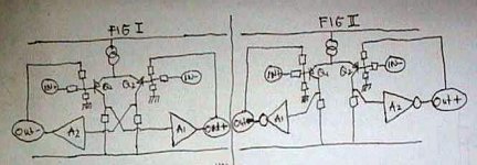
So an idea of questions comes in my mind. I dont really understand why inverting power amp is said to excel the normal one. Fig 1 is the normal X amp, while A1 and A2 is a "Normal Current Gain".
Let's pretend that we can make an inverting current gain (or inverting feedback) that is as good as the normal one. Our main focus here is Q1 and Q2. A1 and A2 is an "Inverting Current Gain " . If this inverting current gain (or inverting feedback) is applied to X schematic, so it comes to Fig 2.
1. Will this work at all?
2. X is coming from the crossing of input and feedback between the 2 differential transistors. But inverting current stage results in fig2, which has no crossing at all. Is this still can be classified as x circuit?
3. The DC problem with aleph-x is somehow related to "positive feedback", at least that is how I understand it from the GRollins tracking approach. With Fig2, there will be no positive feedback, since the input and output is applied to the same differential transistor. Will this eliminate the DC problem in x circuit?
After reading the whole page of Aleph-X (168 pages), it is clear that X configuration is a good one. Not to mention the comments of those who have built it. No wonder Mr. Pass have make it a patent since 10 years before, before aleph was launched.
In this same website, there are comments about the excel of inverting power amp, especially in the gainclone threads.
So an idea of questions comes in my mind. I dont really understand why inverting power amp is said to excel the normal one. Fig 1 is the normal X amp, while A1 and A2 is a "Normal Current Gain".
Let's pretend that we can make an inverting current gain (or inverting feedback) that is as good as the normal one. Our main focus here is Q1 and Q2. A1 and A2 is an "Inverting Current Gain " . If this inverting current gain (or inverting feedback) is applied to X schematic, so it comes to Fig 2.
1. Will this work at all?
2. X is coming from the crossing of input and feedback between the 2 differential transistors. But inverting current stage results in fig2, which has no crossing at all. Is this still can be classified as x circuit?
3. The DC problem with aleph-x is somehow related to "positive feedback", at least that is how I understand it from the GRollins tracking approach. With Fig2, there will be no positive feedback, since the input and output is applied to the same differential transistor. Will this eliminate the DC problem in x circuit?
Attachments
- Home
- Amplifiers
- Pass Labs
- The Aleph-X