I said all wrong.I'm sorry a lot!thanks!I'm sorry!I didn't read all thread.I don't still know whether the Aleph-X was rewired.I don't still know whether one succed on Aleph-X
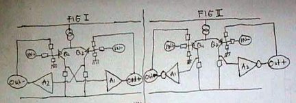
I can't attach my file which was repaired.The right hand of R16 will connect with pin G of Q7 and the left hand of R27 connect will connect with pin G of Q5. Can anyone understand me?
fig 1 use negative feedback and fig 2 use positive
Attachments
NP Wrote: Sorry, I was referring to X amps which have follower output stages. The Alephs and Aleph X can't do that as a practical matter.
OK, so if I keep the Aleph-X circuit as original, and the only change I make is to take the output from the 044 source (source follower), what circuit changes are needed? Using schematic 1.0, I move R42 R43 R44 R45 ( and the output pin) to the source of Q11. But do I take the feedback from the (new) output pin, or leave it at the drain pin of Q11?
Also, what is the overall gain of an Aleph X with source follower output?
Grant
TTH!Can you know a BJT which has got the Hfe curve like MJL3281A?The Hfe curve of MJL3281A is very straight!How cost is it?
The Aleph X thread lurches back to life.
I assume you mean a balanced bolume control. The easiest
way is to use a dual potentiometer with the clockwise contact
going to the signal source, the wiper going to the input of the
amp, and the counterclockwise contact going to ground. One
pot for each of the balanced inputs, meaning a 4 pole pot if you
eant to control both channels with 1 knob.
A good value is about 25K, but you can go higher if you like,
as the Aleph X has a virtual ground input, and doesn't actually
care, although the gain figure does change (but then that's
what you're looking to do, aren't you?) 😎
One of the things I'm planning on incorporating into my next iteration Aleph-X is space on the PC boards for input caps. Well, big deal, Grey...so what? As long as your source is tame in the DC sense, you don't really need DC blocking caps and, in fact, I haven't needed them to date. My intention is to use the space to put in a much smaller value cap to serve as a high pass filter, thus removing the need for several transistors/tubes in the signal path. I used to do this in my old Premier One, but got out of the habit when I wanted to get all the controls in one place. What was once old is new again, and I'm leaning the other way these days. (Not to mention new thinking on the Xenover front. So I'm almost starting from scratch.)
And yes, a level control comes in handy for such things.
Who knows, this silly thread may get to .5M hits after all...
Grey
And yes, a level control comes in handy for such things.
Who knows, this silly thread may get to .5M hits after all...
Grey
Its very hard to get the same current in the differential halves. Inserting 10 ohm before the 390ohm will tell you. Putting current mirror makes the amp doesnt work. The only solution--->match the differential. Is there any other "trick" to make sure both legs of differential have exactly the same current?
If not, how much imbalance is tolerable?
If not, how much imbalance is tolerable?
Current mirrors were invented to seduce people into unwise paths. They certainly aren't going to be of much help in this circuit, especially given that the bias for the output stage will be unpredictable. (Not to mention the fact that they'd ruin the sound of the amp.)
The notion that the current in both sides of the differential must match down to some zillionth of a percent is false--probably PR put forth by the Pro-Current-Mirror tribe. All you need is a matched pair of MOSFETs for the front end and a small screwdriver to turn the adjustment pot for the front end differential.
Note that the two pots I put into the Aleph current sources aren't necessary--I just put them there to have something to fiddle with. After all, a man's got to have something to obsess over...right? I doubt seriously that Nelson has Aleph current source pots in the real XA amps.
One of the alternatives I explored when I was running up the prototype was the idea of using a fixed front end current source, but having the two loads for the differential be adjustable. It works just fine, and you're welcome to try it if you want, but I'd rather adjust one pot than two.
The resistors that Ian suggested certainly help. They lower the value, the less the DC offset, but there's a catch to going too low in that you're trying to match one point in the circuit at ground potential with another one that's about +4V.
The only real alternative is a servo.
Just set the absolute offset to something close to zero and relax, don't worry, have a homebrew...
(with apologies to Charlie Papazian)
Grey
P.S.: Yes, in theory you could use a 2SJ109 JFET for the front end, but there are two problems. One is that the part is only rated for 25V. Why it's 25V when its mate, the 2SK389, is a 40V part is beyond me. Anyway, that limits the rail voltage, hence the wattage. The other limitation is that the '109 won't take the current that the IRF9610 will. That, in turn, has implications as to how many output devices you can drive due to the Gate capacitance. It might work okay for a single pair, maybe two, per side, but I would expect some serious distortion if you start trying to push too many output devices.
An alternative would be to use the 2SK389 for the front end. That would give you a chance to use higher rails. But then you'd have to turn the rest of the amp upside-down and use P devices for the outputs and the small bipolars. You'd still face the current limitation, though.
A more interesting possibility is to cascode the outputs (thereby reducing Gate capacitance) and...
I never said I was done.
And you can bet that Nelson isn't.
Maybe I got answer to my -long ago- question. Once I asked Mr. Pass, why he uses 2 CCS for his SuSy patent, with one small R (100ohm?) connected between emitors.
With 2 ccs it is easier to set both current the same value. The 100R will have the SuSy effect.
But certainly this configuration has less SuSy effect than using 1CCS diffeential, but easier to set the current at both transistor.
With 2 ccs it is easier to set both current the same value. The 100R will have the SuSy effect.
But certainly this configuration has less SuSy effect than using 1CCS diffeential, but easier to set the current at both transistor.
Certainly using two current sources would give you control over the amount of current through each side of the differential, but as you noted, you'd then be forced to separate the sides with a resistor.
You could achieve somewhat the same effect by using one current source feeding the wiper on a pot with each end of the pot going to one MOSFET's Source. However, then you'd get into degeneration (unequal, at that...ugh). That might suit some people, actually--the degeneration, I mean. Lower distortion and all that.
Grey
Yep, thats an option, Grey, but somehow I try to put it for the last effort. RE in differential degeneration may help balance the current in each leg, but it affects the sound (very much to me). They sweep the details. In small BJT differential it is sometimes unadvoidable. Mosfets differential have no problem without RE, due to its natural low gain.
Aleph is such a wonderful design. Compare the parts used with the sound it produces, just wonderful.
Is there any "smart" servo (discrete, without opamp) that can control the share of each leg is exactly the same (but not like current mirror)? Or a "smart" design that can make sure the current in one leg is exactly half of the CCS?
I have noticed that the "smarter" the circuit gets, the less
musical it sounds. No explanation, just an observation. 😎
musical it sounds. No explanation, just an observation. 😎
Hadn't thought about it, really. It's not something I lose a lot of sleep over. I've got something in mind that might work, but I'd have to try it out on the bench before posting and it's a real, real low priority with me. Maybe by the end of the decade.
Wanna get "smart" with a biasing scheme? Take a cue from D'Agostino & Co. and do the processor thing. I've got an old computer I'll donate to the cause...
Grey
Wanna get "smart" with a biasing scheme? Take a cue from D'Agostino & Co. and do the processor thing. I've got an old computer I'll donate to the cause...
Grey
What are you going to do about the sound of the bias
jumping by a quantum leap as a transient occurs? Do you
think that will sound better than just plain old bias?
jumping by a quantum leap as a transient occurs? Do you
think that will sound better than just plain old bias?
You mean like in Star Wars when they make the jump to hyperspace? Setting aside differences in bias, changing the thermal conditions like that bothers me. Gimme that good old-fashioned stuff that runs consistently hot.
Nelson, you're trying to ruin my scheme to get rid of an old PC. I thought I had a foolproof way to get that critter out the door. And, no, I'm not volunteering to do the programming, either.
Grey
Nelson, you're trying to ruin my scheme to get rid of an old PC. I thought I had a foolproof way to get that critter out the door. And, no, I'm not volunteering to do the programming, either.
Grey

D3 and R13 in A40 is StarWars enough for me. Putting microcontroller in bias generator will be a Hi-tech power amp. Read below:
Grey, maybe this current sharing in legs of differential is your last priority, the end of decade thing.
There is an example where this exact current sharing becomes very important. Look at SuSy patent. The living example of this is X1000 power amp. Now we can see why it has 2 CCS, instead of 1 like AlephX use. The exact current sharing between 2 legs is a must here. No compromise, must be stable over time and temperature.
If it has been found out the "smart" way to handle this current sharing, I think X1000 will only have 1 CCS due to better SuSy effect (AlephX has better SuSy effect). At least it will un-plug the recommendation to feed balanced input only to this amp.
I have noticed that the "smarter" the circuit gets, the less musical it sounds. No explanation, just an observation.
Grey, maybe this current sharing in legs of differential is your last priority, the end of decade thing.
There is an example where this exact current sharing becomes very important. Look at SuSy patent. The living example of this is X1000 power amp. Now we can see why it has 2 CCS, instead of 1 like AlephX use. The exact current sharing between 2 legs is a must here. No compromise, must be stable over time and temperature.
If it has been found out the "smart" way to handle this current sharing, I think X1000 will only have 1 CCS due to better SuSy effect (AlephX has better SuSy effect). At least it will un-plug the recommendation to feed balanced input only to this amp.
I think you overestimate the precision of current balance needed for X operation. I believe you'll find that the earlier X models (600 and 1000) used two current sources for power dissipation reasons as much as anything else. The later, smaller versions use a common current path. Nelson has said elsewhere that he had to 'learn' about X as he went along. In the beginning, he used a resistor between the two halves of the differential, but it's certainly not necessary to do so. Nor is it necessary to use two current sources...nor even a current source at all. Current sources, like the cascodes shown in the patent, are incidental to X operation, though they increase the efficiency of the process.
The Aleph-X is no less an X than the X600 and X1000. It's just that I didn't need the resistor in the middle to knock out the so-called "hall of mirrors" effect and the heat dissipation with the (compared to the X600 and X1000) lower rails was modest, so one current source would do just fine. It also allows unbalanced input to the amp.
If you feel that you need to pursue perfectly balanced current in the halves of the differential, then by all means do, but I believe that you'll find that you're looking at the trees, not the forest. It will work, of course, and work well, but it's simply not necessary to get that fiddly about it. Try it and you'll see.
Even after pondering on it for two or three years now, I've only decided to make one minor change in the front end for the next version of the amp. There simply isn't that much that needs changing.
Grey
Output Impedance
I have searched through the thread, and there has been a couple of posts about output impedance of Aleph X, but I could still not figure out how actually to calculate and for that matter meaure the putput impedance, especially with the presence of the Aleph current source.
I have also searched the internet, and you can find tons of equations for common drain or common gate drivers, but nothing on common source.
I know this is trivial, but anyone care to point me in the right direction ?
Thanks,
Patrick
Hi, Grey,
I read here somewhere, that if we use Resistor instead of CCS for feeding differential, it is not good for low voltage. 15V is quite low. What happens if we dont use CCS for this +/-15V AlephX, instead we put 1 resistor that gives 20mA (560ohm) to fed the diff. Is it bad to have this low valued resistor instead of CCS for low voltages? The whole amp will not operate as good as we put CCS instead?
Which is the final schematic drawing up to now? (That everybody agrees). First it is your sch. Then comes up sch with "Magic Resistor".
I still think mainly it is because the difficulty of sharing exact current to both legs. These amp needs exact current sharing, because it uses Folded cascode, the AC current flowing in each leg = the current driving the final stage. If we want both sides operating the same condition, then current sharing in differential becomes important.I believe you'll find that the earlier X models (600 and 1000) used two current sources for power dissipation reasons as much as anything else.
I agree that this current sharing becomes less important, if we talk about AlephX, or 3 stages power amp, because the current in each differential leg is only driving a voltage-drop resistor (for driving the next stage). Remember, that the smaller X amp uses 3 stages, with small Jfet as differential.Nelson has said elsewhere that he had to 'learn' about X as he went along. In the beginning, he used a resistor between the two halves of the differential, but it's certainly not necessary to do so. Nor is it necessary to use two current sources
This is my question, Grey. The AlephX operates on +/-15V rail. The differential is fed with about 20mA CCS....nor even a current source at all.
I read here somewhere, that if we use Resistor instead of CCS for feeding differential, it is not good for low voltage. 15V is quite low. What happens if we dont use CCS for this +/-15V AlephX, instead we put 1 resistor that gives 20mA (560ohm) to fed the diff. Is it bad to have this low valued resistor instead of CCS for low voltages? The whole amp will not operate as good as we put CCS instead?
😀 This is where I stuck right now. Cannot draw anything that works for balancing legs.If you feel that you need to pursue perfectly balanced current in the halves of the differential, then by all means do,
This thread is incredible, almost 300 pages.I've only decided to make one minor change in the front end for the next version of the amp. There simply isn't that much that needs changing.
Which is the final schematic drawing up to now? (That everybody agrees). First it is your sch. Then comes up sch with "Magic Resistor".
- Home
- Amplifiers
- Pass Labs
- The Aleph-X