GRollins said:Ah, but is the fan blowing on the <i>front</i> end?
Bear in mind that the prototype front end MOSFETs aren't next to each other
Grey
Oh but they are in this layout! (see below)😉
Seriously I have directed the fan pretty much everywhere and it doesn't seem to matter.
I got luckyer in my second board, the offset is 40mV there.
All in all I thought this was going to be alot harder, I consider it among the most stable designs I built.
Carpenter,
that's a very nice success story indeed. Also I wish I had a wife that cared. 😉
Attachments

Re: a bit of information to share regarding chokes.....
The two chokes with opposing fields forms a Common-Mode-Choke. I knew those things would work but I got boohoo'ed.😀
http://www.diyaudio.com/forums/showthread.php?s=&threadid=1898&highlight=common+mode+choke
Do you have any pics? Are the chokes directly after the bridges (B-L-C), or is it a PI Filter arrangement (B-C-L-C)?
Rodd Yamashita
John,carpenter said:You'd think I would dwell on my success of having successfully constructed an AX monoblock. Nope; two days of nothing but that annoying hum......
So, today at work, a little voice in my head, you probably know the kind I'm referring to, suggested the strangest thing: switch the power leads on one of the chokes. Only one! I gave it some thought; the chokes are in close proximity to one another due to space requirements. Perhaps the chokes' electromagnetic fields were inducing voltage into one another. Perhaps reversing the power leads on one choke would create a cancellation effect. Hummmmm. The short answer is that the idea worked. The ac ripple out of the speaker outputs was 0.008 volts (very loud on my horn) and now it's down to 0.002 volts! All this from simply reversing the power supply leads on one choke.
I wrote this because I'm truly fond of the sound the AX creates with an L/C filtered power supply; rich, sweet and gutsy! I didn't want to give up the choke. If I were to compare my sound with that of Shawn Wessol's AX I'd say they are like day and night. Shawn's amp sounds great, but on my horns the amp has an edge that grabs the upper high frequencies and casts them in steel. I'm a little bit hard of hearing and didn't mind at all, but my wife with the "golden ears" found it hard to take. The choke has changed her mind and she now favors the AX. I think that the two items go hand in hand. The AX is bright and the choke is a bit dull. Put them together and it's almost like a peanut butter cup.
Sorry for the long winded story, but it had to be told.
John Inlow
The two chokes with opposing fields forms a Common-Mode-Choke. I knew those things would work but I got boohoo'ed.😀
http://www.diyaudio.com/forums/showthread.php?s=&threadid=1898&highlight=common+mode+choke
Do you have any pics? Are the chokes directly after the bridges (B-L-C), or is it a PI Filter arrangement (B-C-L-C)?
Rodd Yamashita
Grey:
How about gain selection with jumpers like XO? It'll give us something to tweak!
Et al:
Several AX's have been built now. Is there sufficient consensus on the schematic and part values to post a final (hehe) schematic?
Between the AX'ers and the Gaincloners this forums starting to get fun again!
How about gain selection with jumpers like XO? It'll give us something to tweak!
Et al:
Several AX's have been built now. Is there sufficient consensus on the schematic and part values to post a final (hehe) schematic?
Between the AX'ers and the Gaincloners this forums starting to get fun again!
Hi Rod,
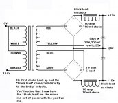
Yes, the chokes are directly after the bridge and then comes the 100,000 uF 25 volt cap per rail. The coils in the iron core choke are laying horizontal and about 1/2" (12.7 mm) apart.
John
BTW, I'm using 10 mH 10 amp chokes from Nebraska surplus sales......
Yes, the chokes are directly after the bridge and then comes the 100,000 uF 25 volt cap per rail. The coils in the iron core choke are laying horizontal and about 1/2" (12.7 mm) apart.
John
BTW, I'm using 10 mH 10 amp chokes from Nebraska surplus sales......
Carpenter
The two coils you talk about, are they in the same channel or is it one coil to each channel?
Thanks!
/Peter
(edited) read the message again and noticed you mention one channel. What is the configuration of the two coils in that PS?
The two coils you talk about, are they in the same channel or is it one coil to each channel?
Thanks!
/Peter
(edited) read the message again and noticed you mention one channel. What is the configuration of the two coils in that PS?
Tweak? The man wants tweak???
Oi!
I thought having three pots would be enough for the tweakers, but perhaps not.
If you want to change gain, you've got several options. You can:
--Change the feedback loop (R16 & R30)
--Change the ratio of the resistors in the inputs (R18/R19 & R20/R29)
--Change the loading of the front end differential (R23 & R25)
--Redesign the front end to have either active load (i.e. current sources or current mirrors) or as a cascode
Etc. etc. etc.
Note that all of these effect other things. The feedback ratio, for instance, will change the gain, but will also change the distortion characteristics. If you get really radical and throw in a cascode, you're going to have to do some serious thinking about how that's going to influence the DC offset on the load resistors...which in turn biases the output MOSFETs.
The design looks complicated, but isn't really. Just take a blank piece of paper and cover half of the schematic. Suddenly, you're back to something very much like the original Mini-A from whence it came. (I have a master plan, you see...everything dovetails together...) If you've got sufficient parts on hand, you can build a Mini-A and test any ideas on it before trying to fit them into the Aleph-X. Remember, I tried to make the Mini-A a 'cheap' project. There will be some things that don't translate exactly--in particular things that relate to output DC offset, but many things will and the Mini-A is a great test bed for possibilities.
Grey
John,
SSN, I knew it! Are those things really 10 amps? Can you measure the wire gauge with a caliper and report back?I am assuming that you are using 2 coils/chn or that you are biasing at less than 5 amps each chn. What is the secondary voltage on your transformer?
Rodd,
with my marginal knowledge of the subject.
The sense of circulation of the current in relation to where the 'dot' that indicates the sense of winding is on the coil winding. Conditional of my understanding of what John has done he has now connected the windings with the same phase or polarity, whatever you want to call it, with the current circulating so that the fluxes are now additive. While before the "dots" on the coil where both on the bridge side. I think he has in essence decoupled the coils.
On an "intuitive only" level I can see why he was getting an high frequency noise from trying to null the ac like you do in a line filter without having a completely coupled system, two coils and two cores.
John
what have you done exactly?
Hello
This is my first post to the forum so I'am a newby
I read the whole tread in one day and I like it very much
Now I have a problem
I want to build this amp for my Home Theater and a good 5.1 SACD and DVD audio setup and of course normal stereo
So I want to build 5 amps about 200W output power (not for music but movies) and they dissipate about 600W
That together with other hardware should be roughly 3500/4000W
That will heat up the room quit well 😱
What about the idea to build a Mini A and apply a bank of source followers and bias them to about 50W output in class a
That way I have enough A power for music and also enough high power for the Home Theater setup
But the last question what happens to the sound
Rob
Cascode Current Confusion
"If you get really radical and throw in a cascode, you're going to have to do some serious thinking about how that's going to influence the DC offset on the load resistors...which in turn biases the output MOSFETs."
I assume that Grey is talking about cascoding the differential P channel input pair with another P channel mosfet pair. Adding cascode transitors to the input differential input pair will have NO EFFECT on the DC voltage across the drain load resistors since the drain current is the same for the cascoded or non-cascoded circuit. The current in each drain resistor half the current supplied by the current source for the front end differential pair. Bipolar cascode transistors will change this current related to the Hfe of the cascode transistors and will be typically less than 1% change and most likely have very little effect on the differential or common mode offset voltage of the amp.
A folded cascode front end can also be designed to put the same current through the drain resistors with no trouble but is a more complicated topology with the benefit of lower input capacitance than the all P channel cascode due to the use of N channel input mosfets for the folded cascode. You can also play with transconductance of the input pair by changing the bias current of
the input pair without changing the current through and the value of the drain resistors. This would allow changing the voltage gain of the first gain stage with little effect of the gain and bandwidth of the second voltage gain stage.
Sorry Grey...... Maybe you are the one that needs to be doing some "serious thinking" before throwing observations out without real analysis of circuit changes.
Actually there are some possible tweaks for this and most other amplifier topologies. But they require a little more knowlege of how amplifiers work than many here would be comfortable with.
Using good passive parts, the alternate current source, and some RC filtering for the power supplies would be my first choices for tweaking the amp.
Sorry, Grey:
I didn't mean to open the door for Fred to pounce.
When I said "tweak" I was referring to your preamp project! i.e. use jumpers to select between say 10dB or 20dB. Like McDonald's - A number 3, medium sized, with 10dB of gain please.
A pot, ala Zen Balanced Linestage, is cool but hard to match, so I thought a jumper setup with two or three precision resistors might be neat. Not essential. Just a thought.
P.S. I'm headed for CES next week. Shall I see if I can get Nelson to autograph an Aleph-X schematic for you?🙂
Thanks
Mike
John,
that's exactly how I thought you did it. It makes sense to me that it would work. It always helps to think about which sense the current travels in.
Mike,
do you really care about Fred comments? They could be valid if they didn't have the sore loser coloration and connotation that they have. What's most striking is the fact is that nobody is competing with anybody, the AX design works, everybody is buliding it, listening to it, everybody's very happy. I am sure that if you care enough whatever mods you want to make could be made no problemo.
John, I am assuming that the swap means you only swapped leads and didn't physically flip the choke around. You refer to " the phase" but I think you mean "the magnetic field" are now self canceling. Right?
LC filter and "10 ohm, 5 watt"
John,
I was looking at your picture of your LC filter.
Good work with straightening out your hum
problem. It's a bit like a "humbucker" pickup on a
guitar.
What does the designation "10 ohm, 5 watt" refer to?
Is it a resistance in series with the chokes or
elsewhere? Or something else altogether?
Just curious,
Erik
progress report....
The label "10 ohm 5 watt" was mistakenly left in the drawing. Nelson had suggested using these resistors in parallel with the choke if necessary. I've yet to run the amp on a scope, but will do so when I have the second channel operating. Perhaps I'll get a peek at what the waveform looks like at much higher frequencies.
The chassis I'm using is similar to the one I layed out on my website. I'm using 1"x1/4" (25mm x 6mm) spacers with 3"x1/4" (75mm x 6mm) heatsink fins. Other than fin thickness, the case dimensions are the same. With one channel attached to the heatsinks, the amp is only slightly warm, similar to that of a full coffee mug after it's cooled for 15 minutes. I'm quite suprised at the efficiency of the AX as compared to the Zen, which originally occupied this chassis; the Zen heated the right side and it was very warm, like a really hot coffee mug. Now wasn't that scientific?
You can see the chassis I'm refering to here:
http://home.earthlink.net/~lotusblossom/index.html
more admissions...
I originally had two pcbs populated. I had placed them in the chassis and connected one up to the power supply. I was anxious to hear my amp and didn't want to bother with separate power supplies until later. I dialed in the first board and then shut down the power and connected the second pcb. I threw the switch and dialed in the second pcb. Once adjusted, I moved back to the first board to double check its settings. The DC offset seemed to be acting screwy, no amount of adjustment would get it to zero. The voltage would flip flop from positive to minus in 6 or more volt increments. Suddenly, Q9 fried along with everything downline; the 0.22 ohm resistor and its power FET. This was very strange and just flat blew my mind. The first board was running fine prior to adding the second board. Today, I'm in the process of creating a second power supply for the second board. I'm waiting for the arrival of two 100,000 uF caps and a bunch of 0.22 ohm 5 watt resistors.
As suggested by Nelson, I had 10 ohm 5 watt resistors running in parallel with the chokes. With so much current draw, I think that I may have overloaded the L/C portion of the power supply. I'm not certain. Perhaps the power FET simply blew and shorted out the upline circuit. At any rate, I'm adding another pair of bridges, chokes and caps and will allow them to share the AC from the 500 V/A transformer. I'm only running 12 volt/rail and think that 500 V/A should be enough power.
I've replaced Q9 (it had blackened legs), the 0.22 ohm source resistor, and the power FET (which behaved like a direct short when connected to the FET matching test rig). If anyone has any suggestion regarding possible damage to the rest of the circuitry on this board, please feel free to enlighten me. I'm not to thrilled to experience this type of mishap again.
Thanks for your time,
John
Fred runs on a different set of assumptions than I do (about most everything, it would seem...).
In my case, were I to choose to put a cascode in the front of an Aleph variant, I wouldn't want the extra gain, so I'd use a smaller load resistor...which would drop the DC offset. That would effect the biasing of the output stages.
I didn't think that was all that obscure a line of reasoning. Sorry if I wasn't clearer.
The preamp is on the back burner for the moment. I'm having to redo a bedroom, which involves tearing down some truly hideous wallpaper, repair the sheetrock, and all the other difficulties along the way, including replacing all the baseboard. It's not so much the money I resent, but the time. Oh, well...it's for a noble cause.
Grey
assumtions
Fred runs on a different set of assumptions than I do (about almost everything, it would seem...).
"In my case, were I to choose to put a cascode in the front of an Aleph variant, I wouldn't want the extra gain, so I'd use a smaller load resistor"
Yes I assume that someone who so freely gives design advice so freely would know what he was talking about occasionally.
Adding a cascode (conventional P channel cascoded Channel diff pair to front end of the Aleph) will make very little change in the gain of the first stage of the Aleph due to the small value of the drain resistors. Perhaps if you actually measured something, learned some Spice programming, and read an electronics text once and awhile you might know what you are talking about For someone who is a big a proponent of learning as you are, you constantly astound me. Vague and incorrect design advice does a great disservice to your credibility and the value of your contributions to the forum. I am not the only one who feels this way. If you are going to post generalities be prepared to defend and elucidate your content. Some of us expect people not to make stuff up as they go along, but expect useful and clear content from a long standing and respected member of the forum. I don't think that is unreasonable and hope people expect the same of me.
Hi Fred,
It would help me a great deal if you would enlighten us with your more gentle side. Grey is extremely valuable to this group and I would like to see him treated with respect. There's nothing wrong with disagreeing with someone's opinion. But, being polite is worth its weight in gold.
John
It would help me a great deal if you would enlighten us with your more gentle side. Grey is extremely valuable to this group and I would like to see him treated with respect. There's nothing wrong with disagreeing with someone's opinion. But, being polite is worth its weight in gold.
John
- Home
- Amplifiers
- Pass Labs
- The Aleph-X