Thanks, wuffwaff, according to the user manual, the NFB has been decreased, but I can see that there is not much decrease in negative feedback 0.1 to 0.091?
Is my thought of dynamic feedback correct?
I will think further about your point about current limiter fr output. I'm running spice simulation and I hope i can visualize this point there.
Thank you.
Is my thought of dynamic feedback correct?
I will think further about your point about current limiter fr output. I'm running spice simulation and I hope i can visualize this point there.
Thank you.
khooyang said:Thanks, wuffwaff, according to the user manual, the NFB has been decreased, but I can see that there is not much decrease in negative feedback 0.1 to 0.091?
Is my thought of dynamic feedback correct?
Hi,
Without looking back at the earlier circuits, IIRC the A-J has less open loop gain than the earlier Aleph versions. The feedback resistors which set the final 'system' gain (i.e. closed loop gain) are in approx. the same ratio, but as there is less open loop gain in the first place, there will of course be less negative feedback, just as described in the manual.
I don't understand your points about dynamic feedback, but if you look at Nelson's site and read the articles on "Zen Variations", I think that this will help you to understand this circuit.
Regards,
Hi Bodken,
Since there are bypass capacitor (C5, which is 5pF in the schematic) parallel to the feedback resistor (R4), and there is one more capacitor, C1 in series with R3, this contribute to dynamic change in feedback value, especially at high frequency. For very high frequency, C5 is shorted, and all the signals passed thorough this capacitor without passing through the R4, hence, all the output signal are feedbacked to the input. I'm wondering why Mr. Pass design such 100% feedback circuit for high frequency signals.
From simulation, I can see that the bode plot of A-3 has a spike at high frequency (30k~300k). I'm wondering Mr. Nelson purposely have 100% feedback at high frequency to eliminate such spike in order to fully emulate tube amplifier as we know that the output transformer's impedance increase linearly with the log of frequency, which will cancle high freqnuency components 🙂.
Thanks for your explanation about the NFB. But I don quite agree that the decrease in open loop gain will reduce negative feedback, there are different. Let G be the open loop gain, and H be the feedback gain, then the transfer function of this closed-loop system can be written as Tf=G/(1+GH). If G is large, then Tf ~= 1/H, which is 10 for A-3.
Thanks for recommending the site about Zen variation 🙂
Hi,
C5 is merely to ensure HF stability, and some people apparently find this is unnecessary in certain Aleph circuits. It will affect the square wave response at HF, and using C5 should help to prevent any unwanted ringing.
The precise value ideally needs to be determined by 'scope measurement when the circuit is constructed, as the chosen layout etc. will probably affect this area.
I don't have details of all of these amps to hand, which is why I said "IIRC", but I think that Nelson was referring to there being less negative feedback than with his previous designs when he said that the negative feedback had been reduced.
Therefore (and if I am right here) if there is less open loop gain but the same system gain after application of negative feedback, the actual amount NFB will be less. I don't have time to look into this fully right now, but this is what I recall from memory.
I think a lot more will become apparent after you have looked at the articles which are on Nelson's site.
Regards,
Hi Bob,
You are right, this C5 can cause smoothing of high frequencies. Recall from Fourier series, the square wave is formed by even and odd harmonics of the fundamental frequency. By canceling the high order term, the square wave will never be square like original.
But our ear like to hear frequency with certain bandwidth. Hence, by applying such dynamic feedback, the high frequency terms can be canceled. And, unlike the normal R-C filter at the signal path, this R-C circuit will not affect the music reproduction, and I especially dislike capacitor coupling at the signal path.
Therefore, we sometimes experience listening to solid-state amplifier where at first it sound nice, a lot of details, but after listening for certain period, we feel that the amp. don't sound natural but sound a little sharp, and we return the amplifier. High frequency cause the ear to feel tired after all. Therefore, Mr. Nelson apply the dynamic feedback to cancel such high frequency.
The above are my experience, but don't apply generally. thanks again 🙂
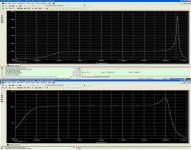
please see my simulation for Aleph 3 with and without dynamic feedback. The first figure shows the bode plot of A3 with fix feedback, and the 2nd figure shows the bode plot of A3 with dynamic feedback.
Please comment 🙂
You are right, this C5 can cause smoothing of high frequencies. Recall from Fourier series, the square wave is formed by even and odd harmonics of the fundamental frequency. By canceling the high order term, the square wave will never be square like original.
But our ear like to hear frequency with certain bandwidth. Hence, by applying such dynamic feedback, the high frequency terms can be canceled. And, unlike the normal R-C filter at the signal path, this R-C circuit will not affect the music reproduction, and I especially dislike capacitor coupling at the signal path.
Therefore, we sometimes experience listening to solid-state amplifier where at first it sound nice, a lot of details, but after listening for certain period, we feel that the amp. don't sound natural but sound a little sharp, and we return the amplifier. High frequency cause the ear to feel tired after all. Therefore, Mr. Nelson apply the dynamic feedback to cancel such high frequency.
The above are my experience, but don't apply generally. thanks again 🙂
please see my simulation for Aleph 3 with and without dynamic feedback. The first figure shows the bode plot of A3 with fix feedback, and the 2nd figure shows the bode plot of A3 with dynamic feedback.
Please comment 🙂
Attachments
Hi,
I'm sorry but I don't have time to go into this any further, and I have not (yet!) built any of Nelson's designs, although I have looked at some of the schematics quite closely.
When Nelson commented that in this A-J he had reduced the feedback, I was initially puzzled on seeing that the feedback resistor values were in the same ratio.
Having discussed this with another Member here, who did some SIMs IIRC, the conclusion reached was that the gain prior to applying any feedback was less than in most earlier Aleph designs, probably due to the use of the J-Fets at the front end, but I don't recall why as this was some months ago.
It is this, we believed, with the consequent lesser feedback resulting from less gain in the first place which gave rise to the comment of 'overall' lower feedback in this design, although the feedback ratio is apparently similar.
Maybe someone else can help you better here.
Regards.
Bobken said:When Nelson commented that in this A-J he had reduced the feedback, I was initially puzzled on seeing that the feedback resistor values were in the same ratio.
Yes, the JFETs have lower transconductance, and so the open
loop gain is proportionately lower. The gain, set by the feedback
resistors, is essentially the same, but there is less feedback.
As the JFETs are more linear, the increase in distortion is less than
the reduction in feedback.
Thank you Mr. Nelson for clarify my doubt. Could you please explain the main reason of adding C5 across R4 which forms a low-pass filter for high frequency signals? From Spice simulation, I observe that the cut-off frequency is about 30kHz.
Is this added to emulate the effect of output transformer in tube amplifier design?
Thank you 🙂
Is this added to emulate the effect of output transformer in tube amplifier design?
Thank you 🙂
1/(2 x Pi x R4 x C5)=144KHz
I think that R1 and Ciss of a 2SJ109 are more important
for cut-off, it should be somewhere around 70-80KHz.
Similar number are in OM for Aleph J.....
PS
Hello guys, this is my first post on Pass Labs
I think that R1 and Ciss of a 2SJ109 are more important
for cut-off, it should be somewhere around 70-80KHz.
Similar number are in OM for Aleph J.....
PS
Hello guys, this is my first post on Pass Labs


radule said:1/(2 x Pi x R4 x C5)=144KHz
I think that R1 and Ciss of a 2SJ109 are more important
for cut-off, it should be somewhere around 70-80KHz.
Similar number are in OM for Aleph J.....
PS
Hello guys, this is my first post on Pass Labs
You are right. Since 144kHz is far beyond 80kHz, there must have some significant meaning why Mr. Nelson choose to include this low pass filter 🙂.
If you lump R4, C5, R3, and C1 together, it is in fact a band-pass filter 🙂.
Luke said:how could you match the gain on both aleph 2s and aleph J for biamping?
it's already same
feedback resistors ( which define gain) have the same ratio :
J: 221K/22K
2: 100K/10K
Hi,
I will start to build my Aleph J in some days so I have some questions.
I have 3 way speakers with 8 ohm and 87db W/m. I am thinking about to double bass and mid chassis to rise sensitivity to about 90 dB but than I have 4 ohms. The Aleph J delivers only 15W at 4 ohms. So would it be an advantage to have the bigger speaker with 5 chassis and 4 ohms or stay with the 8 ohms and 3 chassis (and why) ?
Regards
Thomas
P.S. Could someone post the link of the Aleph J builder thread? I am to dumb to find it.
one additional question:
Isn't it a little bit exceptional that the power is 30W at 8 ohm and 15W at 4 ohm? This statement came from NP so I didn't dare to contradict because I am a non-technician. But what is the reason?
Normally it is the other way around 15W/8 and 30W/4?
Isn't it a little bit exceptional that the power is 30W at 8 ohm and 15W at 4 ohm? This statement came from NP so I didn't dare to contradict because I am a non-technician. But what is the reason?
Normally it is the other way around 15W/8 and 30W/4?
The AlephJ is a single ended-design. It simply runs out of current.
That applies only to complementary (push-pull) amps.
All the best, Hannes
Normally it is the other way around 15W/8 and 30W/4?
That applies only to complementary (push-pull) amps.
All the best, Hannes
- Status
- Not open for further replies.
- Home
- Amplifiers
- Pass Labs
- The Aleph J