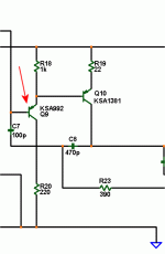
Lets see if i understood the suggested changes correctly:

LTP is now at about 4mA per leg, THD is 0.0044% No change in phase though, looks the same as before.
And heres the ac source in fb loop as suggested:


LTP is now at about 4mA per leg, THD is 0.0044% No change in phase though, looks the same as before.
And heres the ac source in fb loop as suggested:

Last edited:
Your plot doesn't look correct.
You'll need to do as Bonsai said and follow the example set out in the LT samples(?). I use Multisim and it is a bit different.
You'll need to do as Bonsai said and follow the example set out in the LT samples(?). I use Multisim and it is a bit different.
If so, this design sucks!!!
If this plot is correct, you have some work to do.
You have a new tool to work with now, rather than just THD.
Also, try to verify that your device models are accurate, especially the MOSFET models.
Simulation is usually always ideal components in an ideal environment. Stray inductance and stray capacitance are very rarely included in the spice models so i'd expect my amp to be minimum like 1% THD in reality.
Simulation is usually always ideal components in an ideal environment. Stray inductance and stray capacitance are very rarely included in the spice models so i'd expect my amp to be minimum like 1% THD in reality.
It's a bit more complex than that, or so I have heard. There are device models that are far from ideal, in fact they do not work as well as their real world counterpart. This I have seen for myself.
It's quite a leap from .005% to 1%, don't you think? Simulation would be absolutely useless if that was the point spread.
Okok. Well im gonna modify one of the boards i made and try out this new deal and see what it sounds like irl.
Good job! Looks like you've got it figured out. The higher the open loop gain is the lower the THD. Your plot shows the typical THD response that increase with freq. as the loop gain drops. You can play with Cdom now to try to figure out what the smallest Cdom that still gives you stability is. ( your phase margin of 70 degrees is quite high). You could also experiment with multipole compensation. Other things to look at are clipping recovery and square wave response (will show you slew rate and ringing (also a stability clue)).
Ok it works!! Crystal clear highs and good punch in the bass.😀
The downside is that it now has a huge power on BFOOOOMMMMMFFffff lasting 2-3 seconds.🙁
The downside is that it now has a huge power on BFOOOOMMMMMFFffff lasting 2-3 seconds.🙁
It's a bit more complex than that, or so I have heard. There are device models that are far from ideal, in fact they do not work as well as their real world counterpart. This I have seen for myself.
It's quite a leap from .005% to 1%, don't you think? Simulation would be absolutely useless if that was the point spread.
Unless you do something very wrong or drive your amp right to the rails (clipping), I doubt you will ever see 1%. .05-.08% is realistic for a non-beta enhanced design. I had my first creations tested with an HP analyzer. Add 1 small signal transistor (below) and realistically you will only only have .01-.02% or even better (.005%) for real !!
1- $$.03 cent transistor makes a world of difference. 🙂
OS
Attachments
ostripper, im not sure if you saw the schematics posted last:

I have that cobbled together now on one of my boards, i did the darlington alittle ugly on top of the board with 2 transistors.

I have that cobbled together now on one of my boards, i did the darlington alittle ugly on top of the board with 2 transistors.
And heres a pic of the above circuit on a test board:

The gate resistors are still 470 ohms. The "missing" resistors are smds on the bottom side of the board.

The gate resistors are still 470 ohms. The "missing" resistors are smds on the bottom side of the board.
Add 1 small signal transistor (below) and realistically you will only only have .01-.02% or even better (.005%) for real !!
1- $$.03 cent transistor makes a world of difference. 🙂
Hey OS,
I went down that road. Chasing PPM THD on a simulator has lost its shine for me. 🙂
Hitting .01% or lower is more than enough and if it can be done simply and reliably, I'll take that any day.
Spend the time that I'm not wasting on that making my creations look pretty. 😀
PS: Tekko that pic is huge! Maybe scale them down a bit next time?
Last edited:
- Status
- Not open for further replies.
- Home
- Amplifiers
- Solid State
- THD in LTSpice ?


