Member
Joined 2009
Paid Member
It seems non-trivial to get it to fall-over now, even well above 200kHz. Perhaps it's time to go back and lower the feedback network impedance for a better tradeoff against noise.
I've simulated the feedback network with a variable that multiplies the capacitance and divides into the resistance. I can see when 700mV of input at 200kHz causes a transistor to turn off. I can 'safely' halve the impedance of the feedback network from the NAD original but more than that it risks falling-over.
I've simulated the feedback network with a variable that multiplies the capacitance and divides into the resistance. I can see when 700mV of input at 200kHz causes a transistor to turn off. I can 'safely' halve the impedance of the feedback network from the NAD original but more than that it risks falling-over.
Attachments
Last edited:
It seems non-trivial to get it to fall-over now, even well above 200kHz. Perhaps it's time to go back and lower the feedback network impedance for a better tradeoff against noise.
I've simulated the feedback network with a variable that multiplies the capacitance and divides into the resistance. I can see when 700mV of input at 200kHz causes a transistor to turn off. I can 'safely' halve the impedance of the feedback network from the NAD original but more than that it risks falling-over.
This application note might help with calculating different values in your feedback network:
http://www.ti.com/lit/an/snoa586d/snoa586d.pdf
Member
Joined 2009
Paid Member
This application note might help with calculating different values in your feedback network:
http://www.ti.com/lit/an/snoa586d/snoa586d.pdf
That's handy 🙂
However, I got lazy and tweaked the values until my Spice simulation looked OK 🙄
I renumbered all the parts just to ensure sufficient confusion too.
Attachments
My brother felt that in op amp form an inverting design if all active RIAA was preferable. His reason being the non inverting type can never have a gain of less than one. Thus the gain hits a plateau at HF. His view was this causes surface noise to be more noticable. If the slew rate is poor scratches will be exagerated as they have large amounts of > 50 kHz.
If one was to take a 741 and force it into SE class A output with a CCS usually to the -ve rail and use a low noise LTP into the inputs with a passive 75 uS output and active 3180+318 uS I dare say it would sound much better than many would think ( better than some that should sound better ). Micophone preamps were made this way albeit without RIAA. A friend in Pro Audio says the microphone was still the key factor. He updated these to NE5534 when he saw them.
If one was to take a 741 and force it into SE class A output with a CCS usually to the -ve rail and use a low noise LTP into the inputs with a passive 75 uS output and active 3180+318 uS I dare say it would sound much better than many would think ( better than some that should sound better ). Micophone preamps were made this way albeit without RIAA. A friend in Pro Audio says the microphone was still the key factor. He updated these to NE5534 when he saw them.
this sounds like a project I built back in the 1980sMy brother felt that in op amp form an inverting design if all active RIAA was preferable. His reason being the non inverting type can never have a gain of less than one. Thus the gain hits a plateau at HF. His view was this causes surface noise to be more noticable. If the slew rate is poor scratches will be exagerated as they have large amounts of > 50 kHz.
If one was to take a 741 and force it into SE class A output with a CCS usually to the -ve rail and use a low noise LTP into the inputs with a passive 75 uS output and active 3180+318 uS I dare say it would sound much better than many would think ( better than some that should sound better ). Micophone preamps were made this way albeit without RIAA. A friend in Pro Audio says the microphone was still the key factor. He updated these to NE5534 when he saw them.
Flat gain stage, non-inverting, followed by the two larger time constant wrapped into an inverting stage and finally a passive roll off.
I think it was an ETI project.
Member
Joined 2009
Paid Member
Funny thing is the 741 possibly helped everyone build better amplifiers. It reminds me of 1930's petrol engines that just lacked the final touches to make the gimicks work. All the ideas are right. The Rudge Ulster if wanting a point of reference on engines. Rudge were even owned by EMI ( HMV ) and father of Murry Walker was the Ulster winner of the make. The later BSA Gold Star with more tranditional engineering was at least it's equal. I hope the tenuous link with Audio gets me off the hook.
Member
Joined 2009
Paid Member
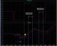
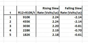
Delightfully weird behavior when stepped parameter t={3,4,5} is marked on plot below with yellow star: output keeps falling when input rises (!)
Slew rate is ~4X the uA741's slew rate.
_
Slew rate is ~4X the uA741's slew rate.
_
Attachments
Member
Joined 2009
Paid Member
Yup, when it falls over, it falls over pretty hard. But it's grown on me, been a vehicle for learning, a fellow traveler. Thanks everyone for their inputs.
I'm going to read up a bit more on active cross-overs, passive filters with unity gain buffers.
I'm going to read up a bit more on active cross-overs, passive filters with unity gain buffers.
Last edited:
http://www.epanorama.net/sff/Audio/Circuits/Misc/Audio Circards.pdf
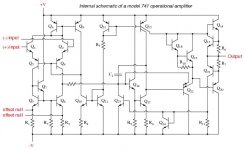
Here is the mighty 741 when loved and respected. The RIAA circuit is interesting if used with ideal gain, I suspect it would if used with a Shure M44-7 be better than imagined. One is allowed to use better op amps. Being Wireless World one should not laugh at it. One has to remember that most op amps are 741's with better slewing and noise, that is pin in out and voltage limits broadly speaking. NE5534 comes to mind. It is said 741 was rejected by the military circa 1963. What 741 did is return us to the time of valves when as a starting point one is plugged in in the place of another. I always use DIL holders as the temptation to change chips can be an afternoons fun. The valves are really very different. ECC82 and 12BH7A can be swapped and often the 7A is better. They are mostly nothing like the same. With op amps they mostly are the same. Many unique musical sounds were found using the wrong valve. With op amps wrong is mostly subjective.
Here is the mighty 741 when loved and respected. The RIAA circuit is interesting if used with ideal gain, I suspect it would if used with a Shure M44-7 be better than imagined. One is allowed to use better op amps. Being Wireless World one should not laugh at it. One has to remember that most op amps are 741's with better slewing and noise, that is pin in out and voltage limits broadly speaking. NE5534 comes to mind. It is said 741 was rejected by the military circa 1963. What 741 did is return us to the time of valves when as a starting point one is plugged in in the place of another. I always use DIL holders as the temptation to change chips can be an afternoons fun. The valves are really very different. ECC82 and 12BH7A can be swapped and often the 7A is better. They are mostly nothing like the same. With op amps they mostly are the same. Many unique musical sounds were found using the wrong valve. With op amps wrong is mostly subjective.
Member
Joined 2009
Paid Member
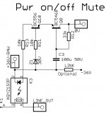
Power up - down mute
I came up with a small circuit for the line-out mute based on a solid-state relay. In this particular case I ended up using the 0V and -Ve rail (rather than +Ve rail and 0V).
A capacitance multiplier is used to create a power-up delay for the relay. It prevents current from flowing through the circuit until the capacitor in it's base circuit has charged up enough to turn on the base-emitter junction and then as the capacitor charges up further the voltage across the circuit rises.
A second device is wired as a voltage sensitive switch. A zener diode in it's base circuit prevents the transistor from turning-on until the voltage has reached a sufficient level.
These two circuit elements work together. Once the capacitance multiplier has charged up for long enough to turn-on the voltage sensitive switch the solid state relay 'closes' and connects the signal to line-out. On power down the voltage sensitive switch will cut-off as soon as the collapsing power supply voltage drops below a certain level.
There's a wrinkle to this story. I can feed the circuit from the -36V rail after the upstream regulator. That voltage rail is available on the pcb since it feeds the shunt regulator. I've allowed for an optional Link to make that connection on the board. But there may be benefit in forsaking this and feeding the -Ve rail from the raw supply before the upstream regulator because the voltage at that point will collapse faster and hence cut-off the signal output relay earlier. I'd have to run a dedicated wire but if I find the power-off circuit needs it to prevent a 'pop' or so on power down then that will be my back-up plan.
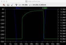
The spice simulation image shows the -Ve rail voltage in blue, it starts at 0V then turns-on, reaching -36V after an exagerrated time frame to make it easy to see. After a delay, the current through the relay (green trace) turns on. After several seconds the -Ve rail collapses back up to 0V and as soon as passes the roughly -25V threshold the relay current turns abruptly off.
(Attachments: the part numbers in the spice simulation won't match those in the layout software - I'm too lazy)
I came up with a small circuit for the line-out mute based on a solid-state relay. In this particular case I ended up using the 0V and -Ve rail (rather than +Ve rail and 0V).
A capacitance multiplier is used to create a power-up delay for the relay. It prevents current from flowing through the circuit until the capacitor in it's base circuit has charged up enough to turn on the base-emitter junction and then as the capacitor charges up further the voltage across the circuit rises.
A second device is wired as a voltage sensitive switch. A zener diode in it's base circuit prevents the transistor from turning-on until the voltage has reached a sufficient level.
These two circuit elements work together. Once the capacitance multiplier has charged up for long enough to turn-on the voltage sensitive switch the solid state relay 'closes' and connects the signal to line-out. On power down the voltage sensitive switch will cut-off as soon as the collapsing power supply voltage drops below a certain level.
There's a wrinkle to this story. I can feed the circuit from the -36V rail after the upstream regulator. That voltage rail is available on the pcb since it feeds the shunt regulator. I've allowed for an optional Link to make that connection on the board. But there may be benefit in forsaking this and feeding the -Ve rail from the raw supply before the upstream regulator because the voltage at that point will collapse faster and hence cut-off the signal output relay earlier. I'd have to run a dedicated wire but if I find the power-off circuit needs it to prevent a 'pop' or so on power down then that will be my back-up plan.
The spice simulation image shows the -Ve rail voltage in blue, it starts at 0V then turns-on, reaching -36V after an exagerrated time frame to make it easy to see. After a delay, the current through the relay (green trace) turns on. After several seconds the -Ve rail collapses back up to 0V and as soon as passes the roughly -25V threshold the relay current turns abruptly off.
(Attachments: the part numbers in the spice simulation won't match those in the layout software - I'm too lazy)
Attachments
Last edited:
Looks like the mute-when-power-is-removed transition is controlled by the ramp up (toward zero) slope of the -36V supply. When it ramps up from -36V to -30V, Q10 cuts off and the solid state relay "contacts" go open circuit 0.1ms to 0.5ms later according to the SSR datasheet.
The slope of the ramp will be dV/dt = (I / C) where "C" is the total filtering capacitance on the -36V supply, and where "I" is the sum of the phono board current (a constant 30mA) plus the line amp board current (another constant 30mA) plus the relay coil currents of the input selector and output selector. Let's make a scientific wild azz guess that it all adds up to 75 mA. If the total filtering capacitance on -36V is 1000 uF then the ramp rate is dV/dt = (7.5E-2 / 1.0E-3) = 75 volts per second. To go from -36V to -30V, where the SSR trips, takes 80 milliseconds.
If AC mains power disappears for 80 milliseconds (or longer), the output mutes. Personally I find this uncomfortably brief. The muting circuits I've built, all include a potentiometer that continuously adjusts the mute-delay-when-power-is-removed. Range is 200 msec to 4.0 sec.
On the other hand, my SWAG of C=1000uF might be waaaay too low or it might be waaaay too high.
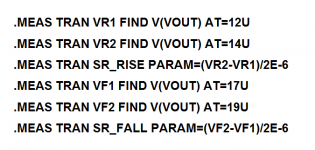
BTW, you might want to attach a couple of LTSPICE .MEASURE statements which print the worst case max reverse bias across the emitter-base junctions of your two BJTs. E-B junctions are easily destroyed with excess reverse bias, which is why datasheets say the Absolute Max is only 5 or 6 volts. Best to double check this in both turn-on and turn-off (and cycle-the-power-switch-rapidly) scenarios.
The slope of the ramp will be dV/dt = (I / C) where "C" is the total filtering capacitance on the -36V supply, and where "I" is the sum of the phono board current (a constant 30mA) plus the line amp board current (another constant 30mA) plus the relay coil currents of the input selector and output selector. Let's make a scientific wild azz guess that it all adds up to 75 mA. If the total filtering capacitance on -36V is 1000 uF then the ramp rate is dV/dt = (7.5E-2 / 1.0E-3) = 75 volts per second. To go from -36V to -30V, where the SSR trips, takes 80 milliseconds.
If AC mains power disappears for 80 milliseconds (or longer), the output mutes. Personally I find this uncomfortably brief. The muting circuits I've built, all include a potentiometer that continuously adjusts the mute-delay-when-power-is-removed. Range is 200 msec to 4.0 sec.
On the other hand, my SWAG of C=1000uF might be waaaay too low or it might be waaaay too high.
BTW, you might want to attach a couple of LTSPICE .MEASURE statements which print the worst case max reverse bias across the emitter-base junctions of your two BJTs. E-B junctions are easily destroyed with excess reverse bias, which is why datasheets say the Absolute Max is only 5 or 6 volts. Best to double check this in both turn-on and turn-off (and cycle-the-power-switch-rapidly) scenarios.
Member
Joined 2009
Paid Member
I am afraid that there will be some kind of 'spike' signal when power is turned off - the phono amp has poor PSRR so as soon as the supply rails start to collapse there will be a signal injected into the phono amp and onto the output. Hence it seems prudent to arrange for as rapid a cut-off as possible. I'm not seeing any harm in cutting it off as soon as possible.
The reverse-biassed e-b junction is protected by the base stopper, is this not enough ? - I know some folk abuse this breakdown to make a fake 'zener' diode out of a transistor providing the current is limited they survive.
I don't really trust spice models to capture this behaviour properly. What I see is maximum -12V reverse bias, but the simulation does not show breakdown behaviour. I read that most transistors rated at 5V to 6V actually break-down around 8v to 9V which is why they are/were popular as 'zener' references.
Last edited:
Gareth,
If the electronic relay is open, obviously it is not open circuit and when coupling into the next stage having gain, could sound leak through the high resistance.
Years ago when first using electronic relays we always needed a second relay that shunts the signal after the one that opens, so it really becomes a potential divider with one heck of a ratio. I take it that this day and age it has changed but I still think that the "open" resistance is finite.
Last edited:
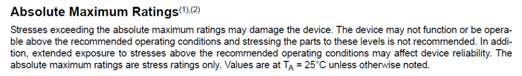
The Absolute Maximum Rating for emitter-base reverse bias is called "VEBO" in the datasheet. Many designers consider Absolute Max Ratings to be sacrosanct, and actually modify their circuit designs to guarantee that emitter-base junctions are not reverse biased by more than 1-2V. Douglas Self's Figure 24.30 in APAD6 shows how he (and others) re-design their circuits to avoid the problem.
When to mute the output after power disappears, is perhaps a matter of taste. Is 1 millisecond too little? Is 1 second too much? I personally don't want a lot of "spurious" muting events when the power company occasionally emits a brief, transient phfart. So I like to think about the delay, expressed in cycles of the AC mains. I don't want to mute if a single cycle of the AC mains disappears and then everything immediately returns back to normal. That seems excessively paranoid.
After introspection and measurement of a few pieces of commercial gear, I settled upon "10 cycles of the AC mains" as my definition of "yessiree bob, this ain't no temporary event, the power is definitely and certainly off". That's 167ms in 60 Hz countries, 200ms in 50 Hz countries. Other people might experience different gutt reactions after introspection. They might even beef up their filter caps to ride out an N-cycle dropout for some surprisingly large value of N.
Attachments
Member
Joined 2009
Paid Member
hmmm, perhaps I can arrange for the power rails to decay relatively slowly.
There is a simpler option, if I accept the risk that some kind of 'pop' can still be produced by the active circuitry immediately that power is removed even though the rails have hardly started to collapse. This simpler option is where I avoid including a dedicated output mute relay. Instead, I rely on the switching relays already in the box.
Without power, the switching relays are designed to allow the pre-amp to be used passively. In other words, these relays, without power, connect the output to one of the line-inputs via the volume control potentiometer; they bypass all active circuitry. These relays will not engage the active circuitry until the unit is powered and only if they are selected to engage active circuitry from the front panel (e.g. phono, tone control, buffer in/out etc.).
I could add a power-on delay to these switching relays to prevent the active circuitry from being switching-in and thus avoid start-up noises from the active circuitry. This is especially important for the phono which has a long time-constant. And if I power these relays from the voltage rails at a point before the upstream regulator then they will also switch off before the active circuitry power rails collapse.
Of course it would mean that as soon as you turn the unit on it will play from the CD input until the turn-on delay has finished and the switching relays change to select an alternative input. And then, when you hit the power-off, the output will be re-connected to that particular line-input rather than having all signal access cut-off altogether. If, for example, you were listening to vinyl, you'd be connected instead to the CD player in the 'passive' mode.
Perhaps this simpler approach is all I need.
Last edited:
I am afraid that there will be some kind of 'spike' signal when power is turned off - the phono amp has poor PSRR so as soon as the supply rails start to collapse there will be a signal injected into the phono amp and onto the output. Hence it seems prudent to arrange for as rapid a cut-off as possible. I'm not seeing any harm in cutting it off as soon as possible.
The reverse-biassed e-b junction is protected by the base stopper, is this not enough ? - I know some folk abuse this breakdown to make a fake 'zener' diode out of a transistor providing the current is limited they survive.
I don't really trust spice models to capture this behaviour properly. What I see is maximum -12V reverse bias, but the simulation does not show breakdown behaviour. I read that most transistors rated at 5V to 6V actually break-down around 8v to 9V which is why they are/were popular as 'zener' references.
Years ago I mixed this idea with muting when the stylus leaves the LP. All it used was rumble from a LP12 ( low ) to activate it. I used an op amp as comparator and 1N4148 as a voltage reference and a further op amp and rectifier to make it work. It was impossible to detect it working except the noise was near zero. Julian Vereker put this idea in my head when he asked me if I had ever heard hiss when the records were playing. The stylus touching the LP helped it get going very fast. I used a mechanical relay. It was fun to hear it click and know it was reliable.
Member
Joined 2009
Paid Member
That's pretty darn clever Nigel !
Mind you, it's a lot of extra bits. I know I can fix the e-b bias risk with a small diode of course. Did you ever post that circuit on the forum ?
Hi Nico - the SS relay will have a very high impedance (10E10 to 10E14 ohms) once off and I believe capacitance leakage will be limited by the pcb trace parasitics but they don't make this very clear. I've uploaded the datasheet.
Attachments
Last edited:
You can use it in this mode, with the usual caveats of Ib max, Pd max, etc, and application notes from major foundries do indeed show many such examples, but you have to use it in this mode only: there will be degradation of linear parameters each time it is done.The reverse-biassed e-b junction is protected by the base stopper, is this not enough ? - I know some folk abuse this breakdown to make a fake 'zener' diode out of a transistor providing the current is limited they survive.
For a transistor used in switching applications, that would be a very minor concern, but for sensitive linear applications it can be more problematic: for the first stage of a mic or RIAA preamp, a single event can ruin the noise characteristics.
Most models do not even include collector breakdown, emitter is even rarer, look for BVxyz in the spice model, but you can add it yourself (preferably with Nc and Ne for realism)I don't really trust spice models to capture this behaviour properly. What I see is maximum -12V reverse bias, but the simulation does not show breakdown behaviour. I read that most transistors rated at 5V to 6V actually break-down around 8v to 9V which is why they are/were popular as 'zener' references.
- Status
- Not open for further replies.
- Home
- Source & Line
- Analog Line Level
- TGMC - a modular control pre-amplifier