Member
Joined 2009
Paid Member
The source of my information in post 478 Musical Fidelity A1 › Technical
Not everything there makes 100% sense to me. For example, it talks about an unbalanced
Fed LTP affecting 2nd harmonic, but in this symmetrical design with complimentary LTP's wouldn't the result of distortion in both of the LTP's together produce symmetrical distortion, I.e. 3rd ?
In both the examples you show the NFB DC blocking capacitors only have to block DC. They don't get presented with any significant AC signal, because the input filter has set the LF passband.I have looked at a couple of Musical Fidelity circuits and seen the low frequency roll offs are not all the same. These depend on the RC relationships in the input coupling and the nfb decoupling circuits.
In the case of the B200 these are 1uF into 33k for the input and 390R into 220uF in the nfb decoupling arm of the feedback circuit.
The respective values for the Class A circuit were 1uF into 47k and 2k7 into 47uF.
I may have not got the right amplifier exactly right with this last one however this is the right area to be looking for reasons for your friends perceptions - low frequency roll off and phase differences.
Maybe Musical Fidelity were my teachers?
The two input filters with 33ms and 47ms time constants allow most of the low bass to pass.
I prefer to go slighlty higher aiming for 80ms to 100ms, but that requires both the NFB DC blocking and the Power Supply to also move to higher time constants.
The single pole at the input dominates, rather than two similar poles combining to give a two pole roll-off that may become unstable, or give rise to peaking in the LF.
Last edited:
if each of the unbalanced LTP create some distortion, it could be luck that some of that increased distortion might cancel in the complementary LTPs.Not everything there makes 100% sense to me. For example, it talks about an unbalanced
Fed LTP affecting 2nd harmonic, but in this symmetrical design with complimentary LTP's wouldn't the result of distortion in both of the LTP's together produce symmetrical distortion, I.e. 3rd ?
But as luck usually has it, it is more likely that the two increased 2nd, increase the total distortion measured at the output.
Does D.Self confirm which distortion becomes dominant when LTPs are not balanced?
if each of the unbalanced LTP create some distortion, it could be luck that some of that increased distortion might cancel in the complementary LTPs.
But as luck usually has it, it is more likely that the two increased 2nd, increase the total distortion measured at the output.
Does D.Self confirm which distortion becomes dominant when LTPs are not balanced?
Samuel Groner had a brief look into Common-Mode distortion http://www.nanovolt.ch/resources/ic_opamps/pdf/opamp_distortion.pdf see page 11.
I remember Linsley-Hood mentioning this last subject 30 or more years ago - somewhat of a bogey to be overcome with one of his low distortion audio oscillator designs published in Wireless World.
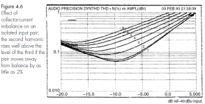
The attention Self gives to distortion harmonic content varies from one edition of his handbook to another but this snip from the 4th edition -2006, discussing the LTP in isolation, might show what imbalance does without becoming a copyright problem here.Does D.Self confirm which distortion becomes dominant when LTPs are not balanced?
Attachments
I built many bipolar and mosfet amps and my experiences are first hand. I must say that MOSFETS sound different from bipolars. Depending on the taste of listener, one may miss warmth and fatness of bipolars in lower octaves, but MOSFETS sound better to me in the HF range, more detail and speed, exactly the same things that JLH mentions in his text. This detail and speed directly translates to musicality. (My comments are for class AB VFA.) I am not saying that I intend to use only MOSFETs from now on. I like bipolars too, but MOSFETs have a distinct subjective advantage for me.
Member
Joined 2009
Paid Member
I have built very good amplifiers with both MOSFETs and with BIPOLARs and did not find that either was deficient in HF or LF. My experience is that the differences in sound, if they exist, are more dependent on the toplogy and other factors. I could imagine that some decades ago power semiconductors were different than the high performance devices I have used - where the fT of the transistors are high enough not to be a limiting factor in the behaviour of the amplifier. I still keep a stock of both types of power device. My best sounding amplifier to date uses BOTH bipolar and mosfet power devcies in the output.
I do remember hearing the JLH Bipolar-FET complimentary feedback pair design in the 1980's and felt it was the amplifier that could do most of the things I liked. Only this week I started to understand why. Realising we are not asking to copy a JLH I ask myself what we could do to make a Naim type circuit better. The two things that come to me to repeat myself is regulated 40V with raw 50V to the final output transistors. Then look to trying to put the dominant pole capacitor away from the VAS. I have no way of knowing how that might work out as I have no example to test. Usually I use the highest gain VAS transistor I can. I did try a Darlington once and felt as JLH might it was a compromise, a good one except I felt there was less detail although more open ( yes I mean exactly that ). However a feedback pair was great although maybe not very different to one transistor of high gain. If going for a Cfbp I suspect D Self type dominant pole is what you must use. The idea here is to ask the minimum amount of current to get the VAS ( TIS ) to swing.
I have 1950's style speakers with punch like a Marshall amplifier. They were designed to use a NAD 3020 but never were used that way, a bit of fun from my audio memory of the Sterling Cinema Kidlington. My friend Martyn knew the set up using BTH amplifiers and baffles as his dad was projectionist at the twin cinema in Witney. My clones favour refinement over raw power in the amplifers as they are as raw as anyone could need. Most of my time is spent trying to make them sound more like a BBC design and to educate myself to turn the volume down. The sound out Naims a Naim. The idea of this system is to play any music and TV stuff. I have that and the big bonus is to make MP3 as good as I can get it. A £20 000 sound as a friend said. Cost me about £300. I don't count my LP12 and 401 as they are my treasures.
If you take my speakers and my Quad 303 ( mildely changed ) it will out Naim the Naim. Trying as many modern speakers as I could I just get nowhere near my sound. A class A amp makes it worse. By this I mean Krell. Even my ex BBC friend who owns it says the same. The big puzzle is her also class A valve Leak stereo 20 will eat it for breakfast. The Leak uses EL 84 valves which in a good design are not unlike transistors in style with walk in depth. I 100% agree with Douglas Self that a good class AB should be as good as a class A and with MOS FET's even more so if you need that. The fact the class AB amp keeps the ripple current as low as it can most of the time is no bad thing ( we never get the ripple rejection in amps we imagine ). If you set up amps to be A or AB I think you will find AB sounds faster and I don't think that's distortion. Why the valve class A and transitor class A is not the same I don't know. Perhaps sliding bias class A is worst of all worlds. The Krell if asking is less musical and boring, the dinosaur Quad 303 is better to my ears ( it was a 10 minutes try out in my system that's been there for two years, the ten minutes to get ideas for EQ as the Quad is better many for that ). I have heard Krell's sound better. Mostly I have heard then sound this way. I don't remember live music sounding closed in and mechanical. Best I heard a Krell was with Linn Isobariks ( LP12,MS The Pre Amp ), it was totally stunning and almost made the Isobraiks sound refined. Trouble is that's two very different worlds coming together that seldom do. Worst was Krell and Martin Logan if memory is right. My speakers do sound coloured against that, all the same it's like food where you want more. Not over cooked.
As far as I know the JLH 10 watt is a constant current class A. If I am right the minimum heatsink was 0.5C/watt. I would imagine better than Krell and maybe up with the Leak. Never heard the Hiraga Le Monstre, could beat them all if reputation means anything.
re post485
We can see that the top most curve (8) where unbalance has reached 10%, that the slope is much lower. I think he states in another part of his book that the slope indicates which harmonic is dominant.
Here he states that 2nd becomes dominant and that seems to fit with the change in slope.
D.Self does not use the complementary LTP, so we don't get to see how the 2nds and 3rds combine in the complementary.
I might be reading too much into my interpretation of that pic (for educational purposes) but the lowest curve (1) for a very closely balanced LTP shows a steeply rising curve once we are beyond noise effects. He is stating this is predominantly 3rd harmonic.The attention Self gives to distortion harmonic content varies from one edition of his handbook to another but this snip from the 4th edition -2006, discussing the LTP in isolation, might show what imbalance does without becoming a copyright problem here.
We can see that the top most curve (8) where unbalance has reached 10%, that the slope is much lower. I think he states in another part of his book that the slope indicates which harmonic is dominant.
Here he states that 2nd becomes dominant and that seems to fit with the change in slope.
D.Self does not use the complementary LTP, so we don't get to see how the 2nds and 3rds combine in the complementary.
Last edited:
I can't say I have much preference for Mosfet output devices either. Some examples of mosfet amplification are very good indeed - as good in subjective sound terms as some of the best LAPT designs. Their real advantage though, is in their toughness - their freedom from second breakdown and fewer concerns with thermal stability. Perhaps its more for these reasons, including substantial price drops, that many manufactures have switched to the few suitable Mosfets still available.
It's pretty clear though, that discrete linear application Mosfets in both Lateral and Hexfet versions have gone nowhere commercially, with still very few types optimised for audio. Only the integrated chipamp versions are fairly recent developments.
1 = 0%
2 - 0.5%
3 - 2.2%
4 - 3.6%
5 - 5.4%
6 - 6.9%
7- 8.5%
8- 10%
It's pretty clear though, that discrete linear application Mosfets in both Lateral and Hexfet versions have gone nowhere commercially, with still very few types optimised for audio. Only the integrated chipamp versions are fairly recent developments.
In case you find the graph confusing as I did, a later edition has a key to the various % current imbalance curves as follows:... this snip from the 4th edition -2006, discussing the LTP in isolation, might show what imbalance does...
1 = 0%
2 - 0.5%
3 - 2.2%
4 - 3.6%
5 - 5.4%
6 - 6.9%
7- 8.5%
8- 10%
I think it is going to depend, as you say, on the actual circuit. Certainly, the surrounding circuit needs to be different for each type to optimize audio performance.I have built very good amplifiers with both MOSFETs and with BIPOLARs and did not find that either was deficient in HF or LF. My experience is that the differences in sound, if they exist, are more dependent on the toplogy and other factors. I could imagine that some decades ago power semiconductors were different than the high performance devices I have used - where the fT of the transistors are high enough not to be a limiting factor in the behaviour of the amplifier. I still keep a stock of both types of power device. My best sounding amplifier to date uses BOTH bipolar and mosfet power devcies in the output.
Aside from the SOA (as Ian points out), FETs are current integrators with non-linear transconductance so it is tricky to make them linear in any way. They don't have perfect square law transconductance so complementary arrangement is not linear either. On the other hand, the hfe of power BJTs can be quite linear over a wide collector current span.
If it's linearity that interests you, of course. 😉
Regarding LTP distortion.
I simulated a pair of BC547C with 1mA tail current, no emitter resistors, fed on the inverting input from a 10mV amplitude sinewave at 10kHz. +/-40V rails.
With perfect Ic balance and 1k in each emitter, H2=-100dB, H3=-50dB.
With 22k in the inverting emitter, H2=-77dB, H3=-52dB.
Offsetting the Ic by 2% (ie: inverting transistor Ic=490uA):
With 22k in the inverting emitter, H2=-57dB, H3=-52dB.
My measurement error is about +/-2dB.
Ian. JLH seems to get a very different outcomes than Self in his application. From what others say John Curl might use something like this in his amplifers. The whole point about complimentary feedback pairs ( Naim lower output using collector ) is local feedback does the best possible job of giving us linearty. In the JLH version it would seem to the casual observer that the FET is vastly better. I was a little surprised by this until I realised how different to a source follower this is. It is almost a horrible corruption of an FET to have a bipolar master device. Then one sees the master bipolar can be very fast and very easy to drive as infront of it is a device that mostly needs no current ( say 2 mA or less ). The bipolar is all the FET needs to fill and empty the gate, a wonderful advantage. Then the minimal transition time. What we seem to have is one fast device that a 1 mA VAS could drive. That seems to say IM, TID or slewing issues should not arise. JLH also says stability improved!!!!!!!!
Getting rid of second harmonic is not the best idea. Like sugar is an OK thing to have. This is a bit like taking natural sugar away from fruit because we can. The curve of the single transistor is a musically ideal curve if musical theory is correct. I suspect it is. I sometimes feel at DIY Audio music is not very much in mind with some people. There is the science of music, it can be helpful to bring it into hi fi. JLH seemed to risk that. He would be shot down in flames now ?
Getting rid of second harmonic is not the best idea. Like sugar is an OK thing to have. This is a bit like taking natural sugar away from fruit because we can. The curve of the single transistor is a musically ideal curve if musical theory is correct. I suspect it is. I sometimes feel at DIY Audio music is not very much in mind with some people. There is the science of music, it can be helpful to bring it into hi fi. JLH seemed to risk that. He would be shot down in flames now ?
Regarding LTP distortion.
I simulated a pair of BC547C with 1mA tail current, no emitter resistors, fed on the inverting input from a 10mV amplitude sinewave at 10kHz. +/-40V rails.
With perfect Ic balance and 1k in each emitter, H2=-100dB, H3=-50dB.
With 22k in the inverting emitter, H2=-77dB, H3=-52dB.
Offsetting the Ic by 2% (ie: inverting transistor Ic=490uA):
With 22k in the inverting emitter, H2=-57dB, H3=-52dB.
My measurement error is about +/-2dB.
NAP 250 looks just like that. It isn't quite the ideal curve. What if 33K was used?
The transconductance of the two transistors is what needs to be matched. BTW this is temperature dependent.
Because the two transistors have different Vce their temperatures will be different. The Vce of the inverting is lower than that of the non-inverting, or about 30V vs 40V. With an Ic of 500uA this is a power difference of 10*500uA=5mW (non-inverting 20mW, inverting 15mW). I found a Siemens data sheet that claims the thermal resistance from junction to ambient for the BC series TO-92 is 250K/W: so a 5mW difference will cause a 1.25K junction temperature difference. The ambient is going to be around 25C (say) or 298K so a 1.25K difference is less than half a percent.
If I've got my sums right, in the Naim circuit the transconductance of the inverting transistor will be a little under 0.5% lower than the non-inverting when their Ic's are identical due to temperature difference.
I don't think a 0.5% difference matters much for Bigun's circuit let alone being that easy to adjust to. Just get their Ic's as close as you can and try for an output dc offset within +/-10mV by select-on-test. 🙂
Last edited:
H2=-60dB, H3=-53dB. (+/-2dB)NAP 250 looks just like that. It isn't quite the ideal curve. What if 33K was used?
Interesting. 30K could be the one if looking for 6 dB.
One must remember the VAS will add some second. What I remember is the NAP total curve for the amp is like a long mirror image Z. The better might be an exponential total if we could. Quad 303 gets close to that.
Must look up Self for Quasi pairs curves. The Baxendale diode makes the lineartiy similar to true complimentray pairs. I would assume Triples either hybrid or all bipolar to be near zero distortion even when no feedback if my experiance of them is typical ( Added to OP604 as a buffer ).
Look to see how low 303 distortion is. Bipolar quasi Triples. Please note how the Triple makes biasing easy as the drift is mostly in the input device. JLH like Sinclair and A&R uses resistor between bases and current source( sink ) with thermal tracking. In the JLH it will work far better.
http://quadrevisionspot.blogspot.co.uk/2010/08/measuring-distortion-with-software.html
Love your Leonardo quote.
Last edited:
My model is unrealistic because I have one base grounded and the other fed from an ideal voltage source. Real base impedances will affect the results. But it gives a reliable indication that adding the collector resistor will increase H2 as will unbalancing the Ic's, but by far the largest affect is unbalancing the currents. In either case the H3 is largely unaffected.
Member
Joined 2009
Paid Member
Are you referring to the closed loop gain that forms a second shelf due to the phase-lead compensator in the feedback network?What I remember is the NAP total curve for the amp is like a long mirror image Z. The better might be an exponential total if we could. Quad 303 gets close to that.
This is a good idea to give this high feedback design some decent phase margin in the 1MHz+ region. A side benefit is to slow down the square wave response so that it doesn't show ringing like some amps and doesn't try to amplify HF noise. I think Naim are quite careful not to introduce HF noise in the first place both with the input LPF and through LPFs in their pre-amps.
- Status
- Not open for further replies.
- Home
- Amplifiers
- Solid State
- TGM10 - based on NAIM by Julian Vereker