I built a modular three-way PA cabinet for Small concerts, it uses a 3 inch compression driver, a 10 inch cone, both horn loaded, and a 15 inch in a ported box.
It's working great, but it needs refining.
My main concern is about the 10 inch driver. It (and the compression driver) are out of EAW KF 650's, but new horns.
I attached a PDF of a driver which I have heard from multiple sources is virtually exactly the same as what they put in the EAW.
The difference in efficiency between the 10" and the 3" is larger than when these were in KF650's. Believe it or not, the sensitivity spec for them were the same in a kf650, and in practice I even backed off the 10" sometimes.
I'm not sure if it's due to the airtight enclosure I made behind the 10" being the wrong size, or the horn change, or something else.
Based on what I learned from helpful people on this site and reading articles, I created an airtight enclosure for the back of the 10 inch driver.
But the volume of my cavity (term?) is larger than the manufacturer specification, and I'm getting ready to address that.
Is that specification a starting point, or something to strive to match precisely? Does what kind of horn the driver is connected to influence how much volume should be behind it? Should I experiment with different volumes, and if so, what protocols/criteria should I use to assess which volume of cavity is best?
Attachments
If the drivers, horns are identical, then yes, otherwise need to optimize them as close as you can and 'it is what it is'. 😉Is that specification a starting point, or something to strive to match precisely? Does what kind of horn the driver is connected to influence how much volume should be behind it? Should I experiment with different volumes, and if so, what protocols/criteria should I use to assess which volume of cavity is best?
Reference:
All driver box loading bandwidth [BW] is defined by its lower, upper mass corner per T/S including horns as proven by both D.B. Keele and Prof. Marshall Leach: http://www.xlrtechs.com/dbkeele.com/PDF/Keele%20(1977-05%20AES%20Preprint)%20-%20LF%20Horn%20Design%20Using%20TS%20Paras.pdf
Note that Prof. Leach chose to use Qes' in lieu of Qts' in his similar paper: https://leachlegacy.ece.gatech.edu/papers/HornPaper/HornPaper.pdf
(Qts'): (Qts) + any added series resistance (Rs)
Last edited:
Last edited:
Note that the EAW KF650 horn is crossed over LR24 at 257 Hz (-3dB point), probably a bit above the horn's cut-off frequency (Fc). In the Bi-amp version, they suggest a BW24 which would put response -6dB at 216Hz.But the volume of my cavity (term?) is larger than the manufacturer specification, and I'm getting ready to address that.
Below Fc, the horn drops at ~12 dB, the 24dB per octave crossover reduces driver excursion below Fc.
The chamber was probably sized for the optimum "reactance annulling" as described in Leach's Horn paper.Is that specification a starting point, or something to strive to match precisely?
Yes, as well as the driver's TS parameters.Does what kind of horn the driver is connected to influence how much volume should be behind it?
A larger compression chamber will result in less level at Fc, the correct size will be maximally flat to Fc, too small will cause a peak somewhere above Fc.Should I experiment with different volumes, and if so, what protocols/criteria should I use to assess which volume of cavity is best?
You can judge by frequency response what best fits your protocols/criteria for your particular application.
Art
Thank you for the responses.
I was able to glean some understanding from those articles, although I can't use the formulas in them because I don't know specifically what kind of resistance the horn is generating.
The only thing I do know is that it is a 7 3/4" opening and does not narrow at any point, it simply opens up.
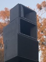
There is a picture in my original post, the horn I purchased for this application features a phase plug, which I originally left in because the 650 had a face plug, but this is a 90° horn, the 90° application in this line of EAW speakers was the KF 695, it does not have a phase plug, and based on some calculations I made today I shouldn't have to worry about beaming if I'm crossing over at 1500 Hz.
So it's gonna be a wide open seven and three-quarter inch hole, only expanding from there. With that in mind, I'm thinking there's gonna be almost no resistance. But then I could be completely wrong. So I'm gonna throw these thoughts out there and see what you all have to say about them.
Would the manufacturers suggested volume for the rear chamber be based on no horn? If so, the little bit of resistance my horn gives would mean I would want to go a little bit smaller than that, right?
I will do a little experimenting, but I'd like to get as close as I can to a good starting point, I'm not a master crafter of speakers and I doubt I'll put that many iterations into this, also my tools for measuring the results I'm getting aren't gonna be that great.
I was able to glean some understanding from those articles, although I can't use the formulas in them because I don't know specifically what kind of resistance the horn is generating.
The only thing I do know is that it is a 7 3/4" opening and does not narrow at any point, it simply opens up.
There is a picture in my original post, the horn I purchased for this application features a phase plug, which I originally left in because the 650 had a face plug, but this is a 90° horn, the 90° application in this line of EAW speakers was the KF 695, it does not have a phase plug, and based on some calculations I made today I shouldn't have to worry about beaming if I'm crossing over at 1500 Hz.
So it's gonna be a wide open seven and three-quarter inch hole, only expanding from there. With that in mind, I'm thinking there's gonna be almost no resistance. But then I could be completely wrong. So I'm gonna throw these thoughts out there and see what you all have to say about them.
Would the manufacturers suggested volume for the rear chamber be based on no horn? If so, the little bit of resistance my horn gives would mean I would want to go a little bit smaller than that, right?
I will do a little experimenting, but I'd like to get as close as I can to a good starting point, I'm not a master crafter of speakers and I doubt I'll put that many iterations into this, also my tools for measuring the results I'm getting aren't gonna be that great.
Some of us were 'raised' on ROT that in general worked 'good enough', though with today's tools is often just a place to start, so based on its 70- 3 kHz rating, tune the sealed rear chamber to: (70*3000)^0.5 = ~458 Hz and get back to us as to how much (if any) you had to adjust it.
The chamber was probably sized for the optimum "reactance annulling" as described in Leach's Horn paper.
Way over my head, though learned from designing reactance annulled BLHs that this is a good ROT, so assume applies to horns in general: Fc = Fs*Qts'/2
(Qts'): (Qts) + any added series resistance (Rs)
The horn is an impedance transformer, a relatively high impedance throat and low impedance mouth.So it's gonna be a wide open seven and three-quarter inch hole, only expanding from there. With that in mind, I'm thinking there's gonna be almost no resistance. But then I could be completely wrong.
I don't know what manufacturers suggested volume you are referring to, but make the rear chamber similar to the volume of the KF 695's if that is the horn you are using.Would the manufacturers suggested volume for the rear chamber be based on no horn? If so, the little bit of resistance my horn gives would mean I would want to go a little bit smaller than that, right?
The driver occupies 1.2 liters of the rear chamber.
It's not the same horn as the kf695, just similar horizontal coverage.
I have no data on the rear chamber of any KF series cabinets, I'm just using a driver from one. That's what makes this tricky.
I have read from multiple sources that the pdf I attached is supposedly the driver that most closely matches what I have.
I have no data on the rear chamber of any KF series cabinets, I'm just using a driver from one. That's what makes this tricky.
I have read from multiple sources that the pdf I attached is supposedly the driver that most closely matches what I have.
Something around the size of the chamber AllenB used for his 200Hz horn will probably be in the ballpark.

What volume are you using now?
Have you measured the response as is, so you can compare changes as suggested in post #6?
Art
What "manufacturer specification" for a horn compression chamber (airtight enclosure) are you seeing for the L10-750YK?I created an airtight enclosure for the back of the 10 inch driver.
But the volume of my cavity (term?) is larger than the manufacturer specification, and I'm getting ready to address that.
What volume are you using now?
Have you measured the response as is, so you can compare changes as suggested in post #6?
Art
I basically just built an enclosure that is square and tight around the driver, no thing inside to make it smaller.What volume are you using now?
Have you measured the response as is, so you can compare changes as suggested in post #6?
Funny, I thought there was a spec, I must have found a website with a calculator that I entered the Thiele Parameters into when I built it (it's been a year and a half). I got a number somewhere that told me I needed to make the enclosure smaller.What "manufacturer specification" for a horn compression chamber (airtight enclosure) are you seeing for the L10-750YK?
HR calcs 458 Hz = 0.4 L, so pretty freaking small to me, so you'll have to back fill yours to go this high.
Ok, so as I suspected, it's most likely larger than it should be.
I'll add fill to one of the pair and compare.
I'm looking for changes in frequency response and I imagine overall efficiency.
Is it best to test at a low or high output level? Will that affect results, or is it linear?
I'll add fill to one of the pair and compare.
I'm looking for changes in frequency response and I imagine overall efficiency.
Is it best to test at a low or high output level? Will that affect results, or is it linear?
The one's I've built and the one I much later simmed in MJK's program looked fine regardless of power input, though 30 W was all that was required to get complaints from miles around due to its extremely high efficiency.  Ditto the small BLH POC using an Altec 802 that came already annulled for wide range use.
Had a bit of fun late one Halloween night when I perched it in front of an open window and played Capital Records' 1963 The Big Sounds Of The Drags Drag Racing Stereo Vinyl LP Record to maybe scare the (vandalizing) teens away and got more than I bargained for with seemingly half the local county police force, etc., prowling around for hours trying to catch them, though did get some teens in the process.
Those were indeed the good ol' days! 🙂 No way I could get away with it nowadays.
Ditto the small BLH POC using an Altec 802 that came already annulled for wide range use.Had a bit of fun late one Halloween night when I perched it in front of an open window and played Capital Records' 1963 The Big Sounds Of The Drags Drag Racing Stereo Vinyl LP Record to maybe scare the (vandalizing) teens away and got more than I bargained for with seemingly half the local county police force, etc., prowling around for hours trying to catch them, though did get some teens in the process.
Those were indeed the good ol' days! 🙂 No way I could get away with it nowadays.
You want the test to be loud enough to be at least 20dB above ambient noise levels, which probably could be achieved with two watts (around 4volts) at 2 meters.I'm looking for changes in frequency response and I imagine overall efficiency.
Is it best to test at a low or high output level? Will that affect results, or is it linear?
Don't expect you will see much of a change in frequency response (or efficiency) within the pass band.
Here are two Hornresp simulations somewhat similar to your horn and driver, the only change being the Vrc (volume of rear chamber) using an 8liter and 26liter volume.
The light gray traces are the smaller chamber:
No effect on frequency response in the 125Hz and above range, and excursion stays under 3mm at 44volts (around 360 watts at the impedance minima of 5.4 ohms) in either case.
The smaller chamber would heat up more than a larger chamber, which would raise the voice coil temperature, resulting in more "thermal compression".
Art
- Home
- Loudspeakers
- Multi-Way
- Testing protocols for ideal volume of sealed space behind horn loaded cone