input cap
I agree. Anyway, when will your amp be submitted to an almost perfect square wave of 10 KHz (not in saturation condition of course)?🙄
Can a source with normal music content and then passing through a pre-amp feed such a waveform to a power amp?😉
Yes, I evaluate the amp with and without the input cap but I consider that the real thing is with the cap and optimise the rest based on that...🙂
AndrewT said:... I do not want to ALTER/MODIFY the amp just for the test, I believe that it should be tested as built.
I agree. Anyway, when will your amp be submitted to an almost perfect square wave of 10 KHz (not in saturation condition of course)?🙄
Can a source with normal music content and then passing through a pre-amp feed such a waveform to a power amp?😉
AndrewT said:I agree with all the above.
What do I read into this following part?
If the amp is bordering on instability when the phase margin is reduced due to feeding a capacitive, then this will show more readily by feeding a squarewave to the input. But if one feeds a square wave to the input of the low pass filter then it is no longer a squarewave (it is a rounded corner approximation with much of the extended hi frequency content attenuated).....
Yes, I evaluate the amp with and without the input cap but I consider that the real thing is with the cap and optimise the rest based on that...🙂

Hi,
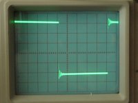
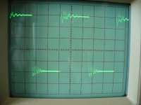
I think that ripple goes on a bit too long. It has little damping indicating that the amp or the output Thiele network is close to oscillating.
I think the 50 to 60kHz ripple should subside to near zero in less than half the period of the 10kHz half wave i.e. in <=25uS.
What's it like with a lower frequency sq wave?

Hi,
That damps out fairly quickly.
Do you notice the frequency is directly related to the capacitance.
It's ringing in the Thiele network we are seeing, but it still seems to last too long
I wonder if the phase margin is a little low?
Could some of our experienced designers step in and offer opinion (or better still quote the builder's bible)?
Hi Guys,
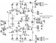
I comeback with this old thread because I make some modifications in my power amp and I don't improved the stability. Somebody can help me? In post #1 is my first circuit: http://www.diyaudio.com/forums/solid-state/117011-better-sound-no.html#post1422579
Thank you! Maxpou
p.s.: I have 1 pair of output and R33, R34 is 47K.
Attachments
Hexfets are fast, and that one isn't so quick for hexfet.Hi,
That damps out fairly quickly.
Do you notice the frequency is directly related to the capacitance.
It's ringing in the Thiele network we are seeing, but it still seems to last too long
I wonder if the phase margin is a little low?
Could some of our experienced designers step in and offer opinion (or better still quote the builder's bible)?
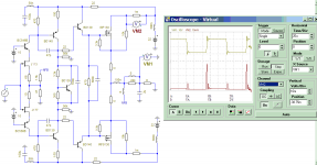
It is looks like ringing is limited for few volts that show it caused by saturated transistors or limited OPS Rds or may be also caused by limited trace capability effect, because if it caused by output inductor, ringing amplitude will also rises. I simulate it with perfect condition it has 40A peak charging output 2uF capacitive load.
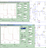
The second picture is simulated my N3 buffer. Not draw huge peak current when loaded with capacitive loads is also important for some cases.
Attachments
Last edited:
Hi Guys!,
nobody can help me with my stability problem. How can I improve it? I tried a Cdom in VAS, decrease the open loop gain with R33, R34 and a input filter. If I put 3 output pairs I improve my stability or no on capacitive load? I would like to know what is the acceptable ringing square wave? thank you! Maxpou
nobody can help me with my stability problem. How can I improve it? I tried a Cdom in VAS, decrease the open loop gain with R33, R34 and a input filter. If I put 3 output pairs I improve my stability or no on capacitive load? I would like to know what is the acceptable ringing square wave? thank you! Maxpou
May be slewrate limiting will help by replacing both 47pf with 220pf. The other way is placing source resistor with value ~0.5ohm and ~330ohm resistor between emitter of driver transistor and output that may help to limit maximum current.
I see this is a sim result and not a true life result, there is a huge difference. I ve built this type amp years ago, its very stable. Also youre probably not going to find a 2uf cap accross a speaker load the way you have it. Show us a real life scope pic of this problem, 10 to 1 is that it doesnt excist. Try use a diffrent transistor for the vas stage, something like 2sa1381 and complement, you can get the device models from bob cordell and see if it doesnt improve.
May be slewrate limiting will help by replacing both 47pf with 220pf. The other way is placing source resistor with value ~0.5ohm and ~330ohm resistor between emitter of driver transistor and output that may help to limit maximum current.
Hi ontoaba and homemodder,
I have tried a input filter 1K serie resistor with 270pF and it doesn't improved. Yesterday I have changed my driver with MJE15030, 31 and nothing change. Like I ask you in another post I make a test with only 1 output pair and not 3 outputs pair like on my pictures. I would like to know if it's my problem?
Home, I have BD139, 140 or MJE340 and 350. I will post some pictures soon.thank you! Maxpou
Hi Guys,
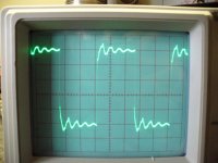
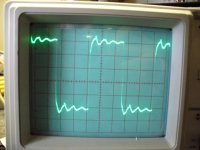
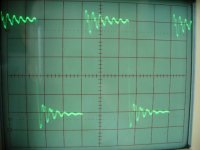
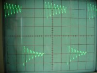
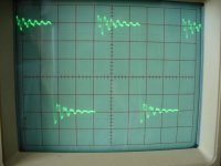
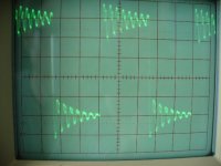
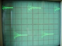
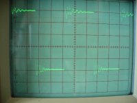
some pictures with and without output inductor. comments. Maxpou
some pictures with and without output inductor. comments. Maxpou
Attachments
Last edited:
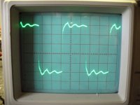
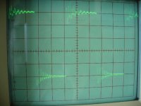
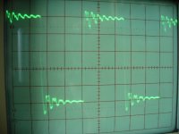
another pictures
Attachments
-
 2SC5171 R33,34=37.5K, L1 2.5uH+4.3ohms.JPG179.9 KB · Views: 85
 -
 2SC5171 R33,34= 37.5K, without L1.JPG181.3 KB · Views: 76
 -
 2SC5171 r33,34= 42K, L1 2.5uH+4.3ohms.JPG174.9 KB · Views: 82
 -
 2SC5171 R33,34= 42K, without L1.JPG180.2 KB · Views: 73
 -
 2SC5171 R33,34= 42K+47pF, L1 2.5uh+4.3.JPG178.8 KB · Views: 77
- Status
- Not open for further replies.
- Home
- Amplifiers
- Solid State
- testing for stability