In Duke58,s defense these are low grade resistors, I have come across them in the past and it doesn't take a lot of movement for the resistor cap to part company from the body.
To me they are "bad news " and as cheap / low noise metal film resistors are available I would keep them out of any sensitive part of the circuit.
Comments in the past have been made in EW/WW on this subject .
To me they are "bad news " and as cheap / low noise metal film resistors are available I would keep them out of any sensitive part of the circuit.
Comments in the past have been made in EW/WW on this subject .
Hello Duncan2-- I can borrow an oscilloscope but only know how to use it to check for clipping and max output. I do see the oscillation on one channel.
I've looked at video on using an o-scope for troubleshooting, but they're all about guitar amps. Can you point me to a video about audio amplifier troubleshooting oscillation with an o-scope?
I've looked at video on using an o-scope for troubleshooting, but they're all about guitar amps. Can you point me to a video about audio amplifier troubleshooting oscillation with an o-scope?
yes, but it’s better to say that they are safe when you connect the capacitor.Unless its the very old type and not a silver mica type I would be dubious that there is leakage in the capacitor.
I have a large collection of quality silver mica capacitors bought decades ago when they were cheap not one has leakage.
As a trial replace it with a quality polystyrene type and check if the same voltage occurs .
Those low values are usually used for stability purposes in high frequency/liability to HF oscillation situations but you haven't provided much information, what is the voltage it is connected across / is it an inter-stage capacitor ?
Hello Duncan2-- I can borrow an oscilloscope but only know how to use it to check for clipping and max output. I do see the oscillation on one channel.
I've looked at video on using an o-scope for troubleshooting, but they're all about guitar amps. Can you point me to a video about audio amplifier troubleshooting oscillation with an o-scope?
I have to apologize as I have blocked most videos on my browsers as on another website I help people with malware / third party information gathering control.
I realize this leaves me at a severe disadvantage but normal practice is to start at the input and work your way through each stage in turn to see how far back it starts to appear.
Normally if its not a component fault causing it, increasing the values--VERY SLIGHTLY of the small value compensation capacitors should show a marked reduction at the output .
A completely amateur method ( but it works ) is to lightly touch various AUDIO components with your finger ( only in low voltage equipment ) ,the capacitance of your body is big enough to remove most oscillations ---in mosfet equipment you must use a "zap-strap".
On the other hand if its a faulty component that wont work .
Maybe. There are other possible problems too.I'm not a technician or EE, but I do know that shorted or open resistors would cause the oddball voltage.
All parts maybe perfect, but a piece of wire running there instead of here can cause an oscillation problem and your method won´t catch that.
A slightly dirty contact, a less than perfect ground, same thing, same consideration.
Again: pulling parts at random trying to solve a problem is NOT the way to go.
Maybe. There are other possible problems too.
All parts maybe perfect, but a piece of wire running there instead of here can cause an oscillation problem and your method won´t catch that.
A slightly dirty contact, a less than perfect ground, same thing, same consideration.
Again: pulling parts at random trying to solve a problem is NOT the way to go.
Any advice on what I should do?
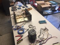
Everything is back together, but the amp is still oscillating, so I tried a little experiment today. Changed just the diff pair (Q501 and Q502) with matched BC550C transistors, then changed to a pair of 2N5961 transistors.
With BC550C transistors (hFE ~595), the amp oscillated. DC Offset jumped around like crazy, but I can adjust offset close to zero and watch it jump around between zero and ~.200 mV.
With the matched pair 2N5961, (hFE ~220), the amp stopped oscillating, but the DC offset won't adjust any lower than ~0.600mV.
Next step (unless someone can recommend something else), is to match all the transistors listed on the schematic.
If that doesn't work, I'm going to convert this thing into a Leach Amp.
Attachments
For a start, could you answer the questions from posts 18 and 19?
By the way, a 0.6 mV offset is really small. An offset of 600 mV would be on the high side.
By the way, a 0.6 mV offset is really small. An offset of 600 mV would be on the high side.
Using high beta BC550C /BC560C in an already oscillating power amp isn't a good idea unless you understand compensation and layout in a power amp design.
I agree with MarcelvdG 600 micro-volts is pretty low.
It is not easy to teach someone remotely from scratch the philosophy of audio power amp design.
I agree with MarcelvdG 600 micro-volts is pretty low.
It is not easy to teach someone remotely from scratch the philosophy of audio power amp design.
A cheap electronic component tester is very handy for checking parts. You will still need to partly remove the component from the circuit.
The DC voltage across C501 should be somewhere in between 0.357 V and 1 V. If it isn't, that can still be due to just about anything.
How did you determine that the amplifier is oscillating? Does it stop when you disconnect the positive side of C502 on the oscillating channel and connect it to ground?
I can see the amp oscillating on the oscilloscope with a sine wave signal input to the Aux 1 of both channels.
C501 voltage accrois C501 reads 0.398 Vdc on both channels.
Does this mean that the values are not reproducible?
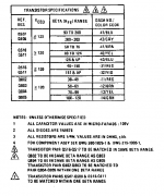
For what it's worth, if everything worked well, you should get something like this:
Base: in between 0.357 V and 1 V
Emitter: in between 0.857 V and 1.8 V
Collector: around -18 V
Then again, when an amplifier is oscillating, that usually results in weird DC readings that can even change depending on how close you are to the oscillating circuitry.
Left channel Q519;
Emitter 0 V
Base 0 V
Collector -8 V, varies up to -12 V after several minutes
Right Channel q519
Emitter 1.28
Base 0.655
Collector -18.32
Thanks for all the replies. I know that it isn't easy to teach someone how to troubleshoot over the internet.
If you have a scope and you try touching/tapping on parts that may be suspect, watch the scope to see how much effect it has on the oscillation, especially if the frequency changes.
The most scientific way to troubleshoot an oscillating amp may be to open the feedback loop and follow a very small signal through all the stages. Somewhere along the way, something would be different on the scope between the two channels.
Otherwise, with a feedback loop closed not only will there be oscillation, but it will be seen everywhere inside the feedback loop. The reason the service manual for the amp suggests checking certain caps is because those are the ones than control phase shift around the feedback loop, and too much phase shift can turn negative feedback into positive feedback (at some frequency). Excessive phase shift, along with loop gain, is necessary for loop oscillation. By the way, what is the frequency of oscillation you see on the scope?
Last edited:
I can see the amp oscillating on the oscilloscope with a sine wave signal input to the Aux 1 of both channels.
Like Mark already asked, at what frequency? Do you also see it without any signal applied to any channel? If not, what happens when you apply the sine wave and then remove it again, does that start sustained oscillations?
C501 voltage accrois C501 reads 0.398 Vdc on both channels.
Left channel Q519;
Emitter 0 V
Base 0 V
Collector -8 V, varies up to -12 V after several minutes
Right Channel q519
Emitter 1.28
Base 0.655
Collector -18.32
You often measure 0 V. That might just mean that the contact between the meter and the circuit is not good. That is a very common problem; pressing the tip a bit harder or slightly scratching the surface of the point you want to measure usually helps, although you have to be very careful that the tip doesn't slide off the point you want to test and causes a short somewhere else.
According to the schematic, the base voltage of Q519 should equal the voltage across C501, so it is a bit peculiar that you get different values.
Was your output offset 600 uV or 600 mV?
Last edited:
Like Mark already asked, at what frequency? Do you also see it without any signal applied to any channel? If not, what happens when you apply the sine wave and then remove it again, does that start sustained oscillations?
You often measure 0 V. That might just mean that the contact between the meter and the circuit is not good. That is a very common problem; pressing the tip a bit harder or slightly scratching the surface of the point you want to measure usually helps, although you have to be very careful that the tip doesn't slide off the point you want to test and causes a short somewhere else.
According to the schematic, the base voltage of Q519 should equal the voltage across C501, so it is a bit peculiar that you get different values.
Was your output offset 600 uV or 600 mV?
I'm using mini grabbers like the attached photo.
The DC offset is 0.6 Vdc. Sorry for my error.
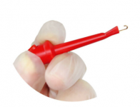
Yes, those very often don't make any contact. You usually have to grab the same point a couple of times until you get a nonzero reading.
One channel is repaired and working. DC offset and bias are adjusted and no oscillation.
For the other channel, I'm waiting to go and get a 3.3 Ohm 1/4 W resistor (R509). It broke while I was mucking about the board.
For the other channel, I'm waiting to go and get a 3.3 Ohm 1/4 W resistor (R509). It broke while I was mucking about the board.
The amp is repaired and working.
I learned a lot about this Marantz 1200. The differential amp pair is most important. With 2N5961 transistors, Hfe ~200, I could not adjust DC offset. With BC550C, Hfe ~600, the amp oscillates like crazy. I took some SPS1958 transistors off the phono board, Hfe ranged from high 300 to 520, and matched a pair in the 420 range.
The amp likes these. DC adjustment was easily made and bias is set at 12 mV on both channels.
Every solder joint was relflowed and every component was checked to make sure it was in tolarance. I spent a lot of time on this thing, but I learned a lot.
I'm moving on to building a Leach Amplifier. Haven't decided if I'll convert the Marantz 1200 and use the Leach Amp 4.5 boards instead of the stock Marantz 1200 power amp boards. It will depend on if the Marantz 1200 can play music for a week without fritzing out.
Thanks for the replies!
The amp couldn't play for a week without the ground hum returning. So yesterday, I took the amp apart, preparing to convert it to a Leach Amp. That's when I found the root of the problem, the RCA connectors for the Amp In. Right and left channels are shown. Only problem is, the amp is torn apart and all the parts are here for the Leach Amp.
What would you do? Install new RCA connectors and put the amp back together? Or, convert to a Leach Amp?


What would you do? Install new RCA connectors and put the amp back together? Or, convert to a Leach Amp?
Attachments
- Home
- Amplifiers
- Solid State
- Testing capacitor in circuit