DaveFred, how's this for an experiment: Try to create a dipole, two tweeters mounted back to back on a baffle that tapers to nothing at the edge, time aligned with delay so that when the waves meet at the edge they cancel?
Best thread of those On the directivity of dipole tweeters
Dipoles were a hot topic in 2005-2015, I learned a lot and got inspired... Thank you all keyser, Rudolf, gainclone, Stig-Erik, saurav etc!
Dipoles were a hot topic in 2005-2015, I learned a lot and got inspired... Thank you all keyser, Rudolf, gainclone, Stig-Erik, saurav etc!
My experiment: mount tweeter at end of a round pipe. Out of doors. No waves will be coming from the back. Just a single dimension (size of pipe) to consider. THEN repeat by mounting on end of a pipe of different diameter. Any changes in the plots should be depend only on the diameter of the pipe.
B.
B.
Dipole is about interference (nulling/summing),sort of diffraction in a way yes. Semantics... any dipole above it's dipole nulling F, will show edge diffractions. But then the response is not dipolic any more...
Dipolplus - Alles über offene Schallwände
In real world the maximum dipole radiation pattern is around 6-8kHz. Smallest planar tweeters have rather wide "baffle" and double domes will have some separation distance between acoustic centers. Good discussion with tests in the thread I linked in post #43
Geometrically, this sounds like a recipe for higher order modes.on a baffle that tapers to nothing at the edge,
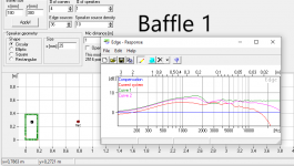
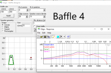
Here are my findings dug from the depths of my HD. Baffle 38x21 centimeters square edged vs Avalon style bevels, on axis and about 30-40 degrees off axis.
Regular baffle:

Beveled baffle:

Regular baffle:
Beveled baffle:
Last edited:
You can't be talking about reducing the dipole moment for these high frequencies, the null isn't the issue, is it? The diffraction itself though I wouldn't agree a naked tweeter would be best. It would involve dissipating front and back independently, preferably before reaching the side as the opportunity is reducing.Yes, impossible to make it small enough as Juhazi says, no better than naked tweeter?
No, I was thinking purely of the diffraction at the edge. It stemmed from a conversation I had with Earl Geddes in the baffle diffraction thread relating to a naked driver with symmetrical front and rear radiation. https://www.diyaudio.com/forums/multi-way/317122-baffle-diffraction-60.html#post6001716 So you'd need a tweeter with no (minimal) baffle
Thanks DaveFred for the dataset -- very much appreciated.
As a tangential question, can we assume that the oh-so-slight waveguiding of the tweeter face plate isn't relevant in the affected region (being more relevant >5 kHz)?
As a tangential question, can we assume that the oh-so-slight waveguiding of the tweeter face plate isn't relevant in the affected region (being more relevant >5 kHz)?
@ Scott. Yes, I'd been following that. However that discussion IMHO is within the constraint of the dipole operating region. Otherwise, there's this.
I tried a similar empirical approach and measured the results almost 35 years ago. I found that the greatest method to minimize edge diffraction effect and improve imaging in a box with a flat soundboard was to NEVER place the driver equidistant to any of any two adjacent sides. In other words, placing the driver off center and at an odd multiple distance from the top of the faceplate works to minimize diffraction. Edge shape had little (negligible) effect until you approached a sphere which is by far the best solution. Use a mirror image for the faceplate of other channel.
- Home
- Loudspeakers
- Multi-Way
- Testing baffle edge treatments for tweeter diffraction.