I obtained a free Simpson AC VTVM a few years ago. As I recall, it was completely dead - no light or anything. Tube complement is 2 12AT7s and a 6C4. On examination, it seems its only problem was the selenium half-wave rectifier went open. I replaced that with a 1N4007. The 6C4 also does not light up, but I will sub another tube to check that. Possible the 6C4 does not show a lot of glow - the 12AT7s glow fine.
Assuming it works now, how do I test it? Then if it works, how to calibrate? There's no adjustment to speak of other than the meter adjust screw on the front of the meter.
Assuming it works now, how do I test it? Then if it works, how to calibrate? There's no adjustment to speak of other than the meter adjust screw on the front of the meter.
Last edited:
On my old heathkit vtvm there was a battery holder for ohms scale. On one of the low voltage DC scales there was a mark at 1.5? Vdc. You got a fresh 1.5 volt not alkaline but old style dry cell and measured the battery and adjusted the meter to match the battery. The zero pot may be for the ohms scale or to 0 the meter as the tubes drift. For the A.c. scale you measured the heater, hopefully at 6.3 volts A.C.. Back when everything was tubes close was usually good enough.

See section 6.5 here. There is an AC calibration adjustment, but perhaps it is not necessary.
Schematic is fig. 7-1.
Bama Manual Archive
Schematic is fig. 7-1.
Bama Manual Archive
Last edited:
Good luck. I'd clean all the contacts, and check the resistor values.
The electrolytics may also be due for replacement.
The electrolytics may also be due for replacement.
Thanks, yes, BTDT re the electrolytic caps. I need to work during the week, so I might not get to it for a few days.
Last edited:
Being an AC VTVM, the trick of calibrating against a fresh flashlight cell is not useful (no AC in a battery).
Initial testing can be against a heater transformer or the 6V winding in a tube amp. Most likely problem is old tarnish: you have to jiggle or beat the probe or switch or tubes to get a reading.
Calibration is basically comparison to a "known-good" AC meter on the same source. If you were a Calibration Laboratory you would have a known-size AC source; but clearly you are not there yet.
Note that this meter has black probe bonded to chassis!! And maybe chassis bonded to wall-outlet 3rd pin ground. One of my first tech jobs, I didn't understand, and blew-out the power in the building.
My apologies. My brain was too slow. Back in the late 60's early 70's, I cant remember exactly, I purchased an AC powered VTVM which measures AC volts, DC volts and ohms. A battery is required for the ohms scale. I also purchased an AC powered Stark tube AC millivoltmeter which had a 0.010 VAC to 300 VAC full scale capabilities. The AC millivoltmeter had a terrible frequency response so I rebuilt it using op amps and put trimmer capacitors across the divider resistors to improve the high frequency response.
I saw VTVM and presumed it was similar to the VTVM multimeter I had.
I saw VTVM and presumed it was similar to the VTVM multimeter I had.
Well, yes and no.🙂Being an AC VTVM, the trick of calibrating against a fresh flashlight cell is not useful (no AC in a battery).
A classic VTVM is *always* a DC measuring instrument, just check classic schematics.
The trick they use to measure AC is thanks to a probe, which does the rectification and conversion.
They generally use 2 kinds:
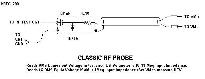
* the "RF probe" type.
It uses a series cap which must also stand any DC voltage present so typically 600V rated, diode (usually Germanium) which generates a positive voltage and a high value series resistor (usually 4M7 or so) which in series with 10M input impedance scales doen the peak rectified voltage to RMS equivalent.
An externally hosted image should be here but it was not working when we last tested it.
*the "Peak to Peak" probe
It uses a full wave rectifier-doubler.
Sometimes a vacuum tube double diode is used, think 6H6, 6AL5 and similar.
Meter panel has a Peak to Peak scale, and old TV schematics included waveforms and their PP values.
So in a way, "DC testing witha battery" is still valid, as long as your AC probe is not damaged.
yes, that is the universal way, works every time.Calibration is basically comparison to a "known-good" AC meter on the same source. If you were a Calibration Laboratory you would have a known-size AC source; but clearly you are not there yet.
...I saw VTVM and presumed it was similar to the VTVM multimeter I had.
Me too.
Well, yes and no.🙂
A classic VTVM is *always* a DC measuring instrument, just check classic schematics.
The trick they use to measure AC is thanks to a probe, which does the rectification and conversion.....
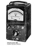
Did you look at the documentation?? This is an AC-ONLY amplifier meter. It will read to 0.03V FS which is well beyond an "RF probe" on a DC meter. It is a cheap version of the Ballantine 300 or the H-P AC-only meters. (Or multisync's Stark tube AC millivoltmeter.)
Attachments
Last edited:
- Home
- Design & Build
- Equipment & Tools
- Testing a VTVM?