Thank you for all the follow-up responses to my further questions!
I am still in the fumbling forties just past 42, without the mathematical acumen needed for all this. I go with the basics, judgement, and my ears. Fortunately, in spite of this, whatever modest designs i have put together, they are liked, and 2 pairs bought by those not after branded goods. 🙂
I will go through the pdf file you have suggested, GM.
Last edited:
Hi
I have a pair of Lowther PM8A Silver coil 15ohm
Does anyone have a plan / the measures for a BIB?
And how deep will it go?
I have a pair of Lowther PM8A Silver coil 15ohm
Does anyone have a plan / the measures for a BIB?
And how deep will it go?
Not on this thread or anywhere on the WWW nor even basic specs I could find, just folks wondering if its specs are close enough to work in existing PM6A cab designs.
So need specs or design would be made per published PM6A specs, i.e. ~44 Hz/2 = ~22 Hz Fb with room gain, how much system output impedance there is determining how ~flat in room it will be.
GM
So need specs or design would be made per published PM6A specs, i.e. ~44 Hz/2 = ~22 Hz Fb with room gain, how much system output impedance there is determining how ~flat in room it will be.
GM
This is the TS for PM8A 15 Ohm with silver voice coil.
Slide the pictures sideways in this ad:
Lowther PM8A Silver coil 15ohm | FINN.no
PM8A are almost identical with PM6A but with a couple of dB more sensitivity. So the answer is that it can be used in PM6A constructions.
Slide the pictures sideways in this ad:
Lowther PM8A Silver coil 15ohm | FINN.no
PM8A are almost identical with PM6A but with a couple of dB more sensitivity. So the answer is that it can be used in PM6A constructions.
I just built a pair of mini bib's. 3fe25 according to the Excel calculator from zilla. 803mm total height and they sound awesome for the little driver! Can do some measurements in Rew if anyone is interested.

Please do as I'm of the opinion that it's more the lack of near/far field measurements than size, especially since it's so adaptable to both smaller and larger spaces, that keeps it from being more popular than it has been to date.
GM
GM
Does anyone have the drawings for the cirkular baffle for 8 inch drivers like cain & cain use?
Not a drawing but it is circular, deep with a large roundover. Using an elipse greatly reduces the diffraction signature of the supraBaffle.
dave
dave
This is the TS for PM8A 15 Ohm with silver voice coil.
Thanks!
 😀
😀GM
Hello to All!
I am on a very modest budget and looking to build a bib. I am keen on using 6" coaxial car drivers for the only reason that they are very affordable and very easily available off the shelf.
My concern is, conservatively assuming an Fs = 75 hz, Qts = 1.0, and Vas = 12.5 l, would they work acceptably as coupled to a bib? I assume these figures roughly based on the data of a few such car drivers (different models by Pioneer & JBL) I had gone through many years ago. I suppose the specifications stay largely similar with these units.
The design I intend is a bib tuned at 60 hz with a 112" long line at 1/2 the wavelength. The internal dimensions could be HxWxD = 56" x 7" x 11.5" giving a volume of about 74 litres.
Could anyone please guide me if such ambition is likely to yield decent results? What should i expect with such a lethargically high Qts driver?
Thanks in anticipation,
sujat
Very cool. I might have to try this as I have the drivers and enough lumber to do it.I just built a pair of mini bib's. 3fe25 according to the Excel calculator from zilla.
When I first looked at your photo, I mistook the curtains for the cabinet and thought "That's a lot of box for a 3" driver!!" 😀
My concern is, conservatively assuming an Fs = 75 hz, Qts = 1.0, and Vas = 12.5 l, would they work acceptably as coupled to a bib?
The internal dimensions could be HxWxD = 56" x 7" x 11.5" giving a volume of about 74 litres.
Greets!
Well, at a 1.0 Qts', the net Vb of a vented or BIB alignment = 20*Vas = 250 L in this case, so reluctant to recommend any smaller without measured specs, i.e. either smaller Vas and/or < 1.0 Qts'.
Not too good with formulas, so rearrange to find the specs needed for 114 L or whatever max size you can tolerate: Vb = 20*Vas*Qts'^1.25
Qts' = Qts + any added series resistance [Rs]: HiFi Loudspeaker Design
GM
Thanks a lot for your inputs and guidance, GM. Much appreciated.
I am not at all good with algebraic or mathematical equations either. Nonetheless, i will explore this formula and see how far I can go stressing it to my tolerance! 🙂
I am not at all good with algebraic or mathematical equations either. Nonetheless, i will explore this formula and see how far I can go stressing it to my tolerance! 🙂
Last edited:
You're welcome!
Sometimes folks here will 'step up', but mostly I've relied on a math/computer whiz buddy that diabetes finally did in recently, so got to find another or breakdown and buy one of those math solver programs.
GM
Sometimes folks here will 'step up', but mostly I've relied on a math/computer whiz buddy that diabetes finally did in recently, so got to find another or breakdown and buy one of those math solver programs.
GM
Well faking things something chronic, call Qe = 1.25 & Qm = 5.0 for the guessed Qt of 1.0. Assuming the guessed 12.5 litre Vas & 75Hz Fs, and making the further SWAG of an Sd of 130cm^2 and an 8ohm nominal impedance, we have a B*L of about 5.1.
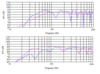
Assuming a ~'typical' 0.5ohm series R for connection, wire loop resistance, with your 112in line & stated Vb, you'll probably have a bit of a bumpy old time of it but (but) the actual horn output is moderately flat in the LF. So providing you don't have a room mode coinciding with the ~70Hz peak in output (a 1/2 space sim only) you may get away with it. Possibly. This is almost pure speculation though, so YMMV applies even more than it usually does. 😉
Assuming a ~'typical' 0.5ohm series R for connection, wire loop resistance, with your 112in line & stated Vb, you'll probably have a bit of a bumpy old time of it but (but) the actual horn output is moderately flat in the LF. So providing you don't have a room mode coinciding with the ~70Hz peak in output (a 1/2 space sim only) you may get away with it. Possibly. This is almost pure speculation though, so YMMV applies even more than it usually does. 😉
Attachments
Well faking things something chronic, call Qe = 1.25 & Qm = 5.0 for the guessed Qt of 1.0. Assuming the guessed 12.5 litre Vas & 75Hz Fs, and making the further SWAG of an Sd of 130cm^2 and an 8ohm nominal impedance, we have a B*L of about 5.1.
Assuming a ~'typical' 0.5ohm series R for connection, wire loop resistance, with your 112in line & stated Vb, you'll probably have a bit of a bumpy old time of it but (but) the actual horn output is moderately flat in the LF. So providing you don't have a room mode coinciding with the ~70Hz peak in output (a 1/2 space sim only) you may get away with it. Possibly. This is almost pure speculation though, so YMMV applies even more than it usually does. 😉
Scottmoose, even though we are dealing with more of an optimistically hypothetical driver, the time and energy you have put in to simulate the response is a windfall for me. I feel grateful. For someone who was in the dark till now, this response simulation, although only indicative, is a lush green oasis! It gives me a very useful platform to speculate upon through visualisation. Thanks a lot! 🙂
1. One rectification though, in case it has any effect on the simulation. All these car drivers are nominal 4 ohms units.
2. If I add some damping material in the path immediately beyond the driver (in addition to the usual places as suggested), will it help tame the bloat to a degree?
3. Such a driver as simulated in a 14 l sealed box in WinISD reaches a hypothetical peak Xmax of 2 mm at about 8 watts. Would it be better off in a bib with the 112" wavelength loading supporting the excursion?
4. Due to what are the two SPL graphs in the image different from each other?
5. I am not familiar with much of abbreviations.... so YMMV is? 🙂
6. With such big boxes and larger surfaces, is it advisable to lightly crossbrace the sides in the 2nd half? Would I be hearing much of the box otherwise?
Thank you.
Last edited:
You're welcome!
Sometimes folks here will 'step up', but mostly I've relied on a math/computer whiz buddy that diabetes finally did in recently, so got to find another or breakdown and buy one of those math solver programs.
GM
I am confident that you WILL rise to the occasion and "step up", GM! 🙂
Last edited:
I have read in passing some posts of the long discussion on the subject but I have not found anything about the possibility of using 2 identical drivers placed close together.
Is it a feasible solution or does it not bring advantages?
If feasible, how should the acoustic load of the box be calculated?
Is it a feasible solution or does it not bring advantages?
If feasible, how should the acoustic load of the box be calculated?
elleman said: "I just built a pair of mini bib's. 3fe25 according to the Excel calculator from zilla. 803mm total height and they sound awesome..."
They look great! Enjoy.
They look great! Enjoy.
2 identical drivers placed close together.
If feasible, how should the acoustic load of the box be calculated?
Not a problem, just put them on either side of a single driver's location and in theory/reality since the Vas spec sums [2x for identical], so does calculated net volume [Vb], i.e. input the driver's specs with 2x Vas per the earlier posted formula: Vb = 20*Vas*Qts'^1.25
This results in an acoustic +3 dB and another +3 dB for doubling of power [assuming the amp has it available of course].
GM
Last edited:
- Home
- Loudspeakers
- Full Range
- Terry Cain's BIB -why does it work and does anyone have those Fostex Craft Handbooks?