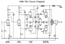
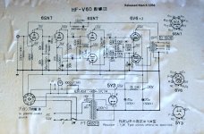
2X 6SN7s makes considerable sense. That fits right in with Williamson style circuitry. I've uploaded the original schematic. 2X of the same triode found in a 6J5 are inside a 6SN7. 😉 So, 2 bottles, instead of 4, take care of the power section's small signal circuitry. The 2 bottles don't have to be "matched", but good section to section balance in the bottle used for the differential amp is in order.
While Williamson triode wired his O/P tubes, scads of Williamson style amps have been built using full pentode and ultra-linear mode "finals".
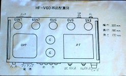
What has me scratching my head is the non-linear 6SG7. That fits in with a conversion to guitar amp, AKA distortion machine. Perhaps Pioneer used the 6SJ7, in a HIFI configuration. Except for the internal g3 to cathode connection in the 6SG7, the 2 types appear to pin out the same.
While it would be neither inexpensive nor simple, I do see a possible path to a stereo setup. Hashimoto may very well offer the O/P transformer used, currently. Williamson style circuitry is discussed, in abundance, in the DIY Audio archives.
While Williamson triode wired his O/P tubes, scads of Williamson style amps have been built using full pentode and ultra-linear mode "finals".
What has me scratching my head is the non-linear 6SG7. That fits in with a conversion to guitar amp, AKA distortion machine. Perhaps Pioneer used the 6SJ7, in a HIFI configuration. Except for the internal g3 to cathode connection in the 6SG7, the 2 types appear to pin out the same.
While it would be neither inexpensive nor simple, I do see a possible path to a stereo setup. Hashimoto may very well offer the O/P transformer used, currently. Williamson style circuitry is discussed, in abundance, in the DIY Audio archives.
Attachments
Thank you very much Eli. I understand the dim bulb testing now to check cap and transformer. I also am reading the safety thread pertaining to high voltages.
If I could turn to stereo I'd definitely want that. Im more than willing to take on the challenge.
Is that the hysteresis loop coming of the secondary output coil with 5k resistor?
Looking at what seem familiar to me first.
Feed me more please..... as i feel bitten. These things are very beautiful as I'm sure you all know. I remember not having flatscreens, VCR's and microwaves in the home. I'm not that old but Im not that young either. I remember having a pager now I'm stuck with an edge 6s galaxy. A blood suckers bill compared to the 10.00 a month pager and quarter......
Hugh
Last edited:
The 5 Kohm and 470 Ω resistors constitute the global negative feedback (GNFB) pair. 8.6% of the amp's O/P voltage is being fed back.
When NFB is applied to a cathode, as is the case here, that signal has be in phase with the I/P signal. OTOH, if NFB is to be applied to a grid, it has to be out of phase with the I/P. O/P transformer wiring can be manipulated to get whatever phasing is necessary.
When NFB is applied to a cathode, as is the case here, that signal has be in phase with the I/P signal. OTOH, if NFB is to be applied to a grid, it has to be out of phase with the I/P. O/P transformer wiring can be manipulated to get whatever phasing is necessary.
Hi,
Is there a book I can read that explains the different styles and gives definitive meaning to most of the Jargon ill encounter?
Is there a book I can read that explains the different styles and gives definitive meaning to most of the Jargon ill encounter?
Last edited:
Run a Google search for NEETS. NEETS is U.S. Navy training material available gratis off the WWW.
NEETS will keep you busy, for a while. After "digesting" some of what you learned, visit a collegiate library and take a long look at the 1st or 2nd edition of "Basic Electronics for Scientists" by James J. Brophy. Prof. Brophy will take you "down the garden path". The text provides excellent foundation material about both tube and SS devices.
More specific to the DIY hobby are the writings of Morgan Jones, which enjoy a stellar reputation.
I don't need that I have an AAS in EE and hold a Machining diploma and 2 certification in manual and CNC machinist and All I want to know is tube amp design.
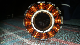
I rewind brushless dc motors for a hobby. I was programming in basic on a vic 20 in the 4th grade. I like to be fully versed on something I haven't ever done before just jumping in. These terms like "o" getter I have never seen before.
Pic programmers built by me no kits boards and all etched by me.
Currently Im prototyping a single phase sector brushless dc motor with parallel slots and measuring core loss in proprietary powder core material blended by myself using a simple Helmholtz coil.
Attachments


Last edited:
I asked about The PCB construction and got no answers. But I own a PCB mill so I could probably fashion something real nice If I wanted to. But I have to be fully acclimated to the Jargon before anyone can really talk to me. The chassis and metal work all not an issue for me. I can hold my own here once I understand all the terminology used.
Thanks for helping most sincerely. I just want you to know we don't have to start at electronics 101. Someone should create a sticky with the general Jargon and what defines "Strong" when I see 50/54 or 1000/950 and they both say they are strong. "d" getter "o" getter this stuff is what I'm speaking of.
Thanks for helping most sincerely. I just want you to know we don't have to start at electronics 101. Someone should create a sticky with the general Jargon and what defines "Strong" when I see 50/54 or 1000/950 and they both say they are strong. "d" getter "o" getter this stuff is what I'm speaking of.
Last edited:
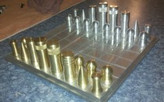
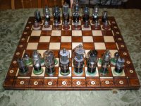
For fun check out this chess set I machined Eli. It was done on a haas mini mill and SL-10 slant bed lathe. I think I received a 98 on this coz he claimed he felt a burr 🙄. The king and queen crowns were done on a Leblonde manual lathe and a knurl tool.
It sold on ebay in days 400.00 smacks. I could make a fortune if I personally owned those 40,000 dollar machines.....
I think I've been bitten because my mind is already running with creative ideas I'm sure you all would like.
So please feed me fellas get me up to speed as soon as possible.
Thanks to you all for your continued kindness time and patience.
Hugh
Attachments
Last edited:
Other members will have to speak for themselves. I have not done a PCB, from scratch, for at least 55 years. Were an attempt be made by me, I'd do it the same old way, with copper foil on FR4 base, resist of some kind, and FeCl3.
Many "vintage" units, along with any number of member projects, are done using point to point wiring.
When you see something like "D" or "saucer" getter, it's the shape of the support used to hold the barium/cesium/rubidium pellet that forms the metallic "mirror" on the envelope's inside, after radiant energy is applied. The mirror is the getter and it "gets" residual O2 that vacuum pumping did not remove.
Those numbers are from tube testers and vary in meaning, depending on model and test conditions. Until you become very experienced, buy your tubes from known reliable dealers.
You said Leblonde lathe. I used a Leblonde "Regal" engine lathe in H.S., back in the early 1960s. FWIW, there are some excellent machining videos on YouTube. Start with Keith Fenner's.
@ Hollow State
I like yours too 🙂
@ Eli
Will have a look. Yes the regal same lathe long and large.
I like yours too 🙂
@ Eli
Will have a look. Yes the regal same lathe long and large.
Last edited:
Late reply, may help someone.
Some schematics attached. Audio Note Kit 4 copied the final stage - check the unusual cathode resistor values. The Audio Note P2-PP is similar, early ones came out with 12AX7, 6SN7 and 6L6 and is 2x20W /side. The AN kit 4 is 2x10 watt. The Sanui UL looks to be 8 watts accroding to the notes made on the schematic.
Am at the moment building the AN kit 4 with Hashimoto OPT's, mains transformer is a Hammond and large enough to drive 6L6's should I want to change from 6V6's.
Cheers
AM
Attachments

I think attached schematic is for one of the Audio Note P1-PP iterations, not sure. Interesting to see that the 47K trimpot in the floating paraphase inverter has been re-introduced.
What is the purpose of C2/C3 in series? (It also seems a little odd that their values are so different than the other coupling cap)
A 47K plate load on a 12AX7...great...
-probably mistake
-not great, uh a big distortion and minimal gain.
-i´d put in middle 12ax7 fet gyrators instead-gain >80x with hard lowZ drive to endstage
-not great, uh a big distortion and minimal gain.
-i´d put in middle 12ax7 fet gyrators instead-gain >80x with hard lowZ drive to endstage
What is the purpose of C2/C3 in series? (It also seems a little odd that their values are so different than the other coupling cap)
Don't know, suspect it has something to do with balancing the response curve.
A 47K plate load on a 12AX7...great...
MAZDA 12AX7 / ECC83 specs attached. 47K is one of the recommended configurations.
@hpeter The Sansui amplifier is a cult amplifier in Japan and highly regarded. The 12AX7 has an amplification of approx 14x.
Attachments
MAZDA 12AX7 / ECC83 specs attached. 47K is one of the recommended configurations.
@hpeter The Sansui amplifier is a cult amplifier in Japan and highly regarded. The 12AX7 has an amplification of approx 14x.
"Recommended" is probably not quite the right word. 12V out at 5% THD is dog poop. The unbypassed cathode resistors everywhere aren't going to help matters.
A 12AT7 or 6922 would do everything better with the available voltage other than acting as a distortion generator.
"Recommended" is probably not quite the right word. 12V out at 5% THD is dog poop. The unbypassed cathode resistors everywhere aren't going to help matters.
A 12AT7 or 6922 would do everything better with the available voltage other than acting as a distortion generator.
Hmmm.... who do we believe? A tube manufacturer from an era when comptetion was fierce? A well respected firm in its day (Sansui) whose products are experiencing a cult status in Japan? A present day firm that is marketing high end products?
Or do we believe some self proclaimed mr know-it-all who does not have any sales results to show?
- Status
- Not open for further replies.
- Home
- Amplifiers
- Tubes / Valves
- Tell me what this is