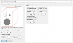
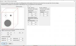
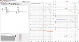
This is the best so far I could come up with designing Teen2020.
Attachments
-
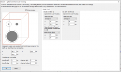
 box.PNG35.2 KB · Views: 145
 -
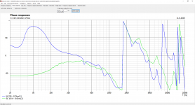
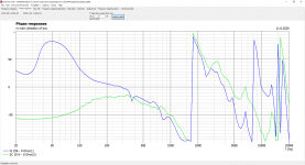 phaseresp.PNG110.5 KB · Views: 54
 -
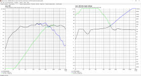
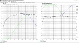 maxspl.PNG144.3 KB · Views: 52
 -
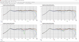
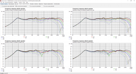 freqrespdir.PNG145.8 KB · Views: 62
 -
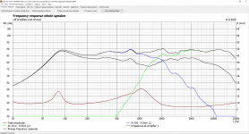
 freqresp.PNG90.9 KB · Views: 55
 -
 driver_w.PNG100.3 KB · Views: 49
 -
 driver_sc.PNG96.6 KB · Views: 133
 -
 directivityplots.PNG134.5 KB · Views: 140
 -
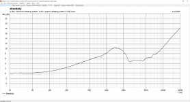 directivity.PNG87.8 KB · Views: 142
 -
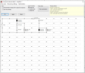 crossover.PNG39 KB · Views: 137
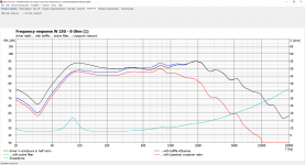
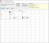
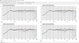
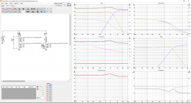
Erkki1 gave me the crossover electrical plan and suggestion was crossover @2200Hz, but didn't have the box optimimized to it. I learned how to do it and the crossover sets to @1720Hz. Some of component values was pretty close to what shop has to offer. I also tried to keep it simple because variance of the component actual values. I ended up crossover @1747Hz.
Ok, just make sure that the tweeter can go as low as you specified in the crossover. I suggest you use erkkis crossover, 2200 hz sounds better imho.
Ok, just make sure that the tweeter can go as low as you specified in the crossover. I suggest you use erkkis crossover, 2200 hz sounds better imho.
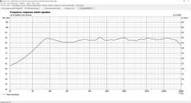
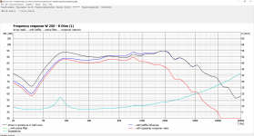
and please check all boxes in the frequency graph.
and please check all boxes in the frequency graph.
Did you mean this? 😉
Attachments
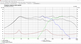
Did you mean this? 😉
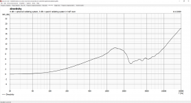
yes, thanks. It gives a good overview of the total spl, the individual drivers and the total impedance.
Last edited:
Boxsim has quite frequently a tendency to move crossover frequecy lower than is good for the tweeter. But the algorithm is propably just optimizing the frequency response. If you want to keep crossover frequency at certain area, you should set some components to a fixed value (= not included in optmization). But, it is an iterative process anyhow.
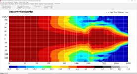
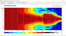
Afterwards it would be interesting to see how the simulation compares to measured frequency responses and polar patterns.
Afterwards it would be interesting to see how the simulation compares to measured frequency responses and polar patterns.
BoxSim actually uses the boxes size. Latest graphs have this correct. Crossover @1737Hz
Attachments
-
 phaseresp.PNG110 KB · Views: 40
 -
 maxspl.PNG144.5 KB · Views: 47
 -
 freqrespdir.PNG144.4 KB · Views: 49
 -
 freqresp.PNG105.2 KB · Views: 50
 -
 driver_w.PNG99.5 KB · Views: 47
 -
 driver_sc.PNG96.7 KB · Views: 44
 -
 directivityplots.PNG134.2 KB · Views: 45
 -
 directivity.PNG88.3 KB · Views: 44
 -
 crossover.PNG37.5 KB · Views: 46
 -
 box.PNG36.3 KB · Views: 64
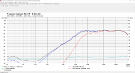
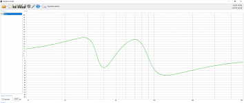
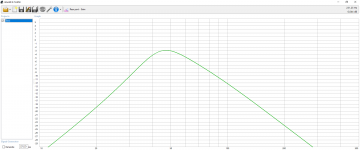
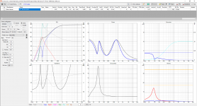
I am currently working on rising the crossover (a) 1737 -> (b) 2170Hz. Frequency Response Direction with 2170Hz behaves differently. There "V"'s don't line up. Does it cause concern?
Attachments

Last edited:
Seems like the supplier of the Original Teen Wall Speakers has come active and is selling it again. I order pair of kit. Only thing open is the box.
So I got honest way out of this desing hassle. 😉
So I got honest way out of this desing hassle. 😉
Original Teen Wall Speaker
Bassdrivers: Nokia Harman LPT 145/25/100FS
Measured parameters:
89.8dB
Re 6.0
Fs 64
Qts .48
Qes .6
Qms 2.3
Le .87
Mms 5.9g
Vas .38 cu.ft. = 10.8ltr
Outer dimension: 145mm
Installation hole: 116mm
Tweeter: Nokia Harman LPKH 50/10/100 SKF
Impedance: 8ohm
Outer dimension 51mm x 51mm
Installation hole 43mm
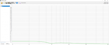
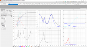
Some checking with WinISD
Bassdrivers: Nokia Harman LPT 145/25/100FS
Measured parameters:
89.8dB
Re 6.0
Fs 64
Qts .48
Qes .6
Qms 2.3
Le .87
Mms 5.9g
Vas .38 cu.ft. = 10.8ltr
Outer dimension: 145mm
Installation hole: 116mm
Tweeter: Nokia Harman LPKH 50/10/100 SKF
Impedance: 8ohm
Outer dimension 51mm x 51mm
Installation hole 43mm
Some checking with WinISD
Attachments
-
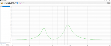
 imppahse.PNG61.8 KB · Views: 51
 -
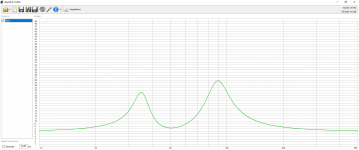 impedance.PNG61.9 KB · Views: 53
 -
 coneexc.PNG60.3 KB · Views: 55
 -
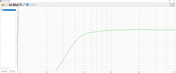
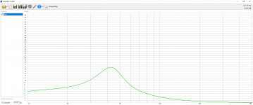
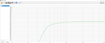 spl.PNG62.8 KB · Views: 48
 -
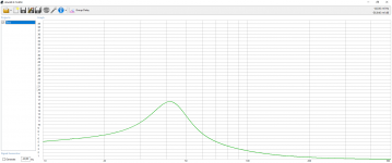 groupdelay.PNG59.4 KB · Views: 45
 -
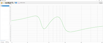
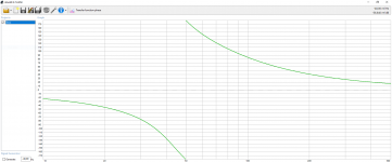 transfuncphase.PNG61.5 KB · Views: 164
 -
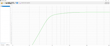 transfuncmag.PNG59.4 KB · Views: 160
 -
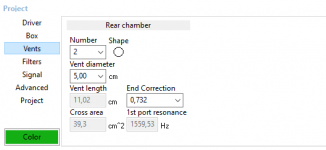 vents.PNG7.8 KB · Views: 169
 -
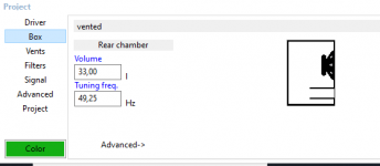 box.PNG7.3 KB · Views: 167
 -
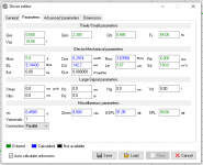
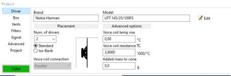 driver.PNG12.9 KB · Views: 168


Support structure takes up some space so actually volume is 31,5L
Attachments
-
 coneexc.PNG60.4 KB · Views: 50
 -
 impedance.PNG61.8 KB · Views: 47
 -
 imppahse.PNG61.3 KB · Views: 50
 -
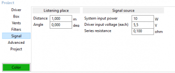 signal.PNG7.7 KB · Views: 44
 -
 spl.PNG59.8 KB · Views: 49
 -
 groupdelay.PNG59.3 KB · Views: 54
 -
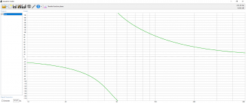 transfuncphase.PNG61 KB · Views: 43
 -
 vents.PNG7.6 KB · Views: 45
 -
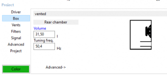 box.PNG6.3 KB · Views: 44
 -
 driver.PNG12.9 KB · Views: 48
The Original Teen Wall Speaker DIY kit was meant to placed at wall. I am thinking about something that is placed 10cm at front wall.
Outside HxWxD
1220*200*216
Inside HxWxD
1196*176*192=40,4L
Chebyshev tuned
Bass reflex tuning frequency Fb=53,7Hz
Bass reflex port 6,1cm long and 5cm diameter
Number of ports 2pcs
Ports face backwards
Probably doesn´t go low as original but gets more power at 50Hz
Outside HxWxD
1220*200*216
Inside HxWxD
1196*176*192=40,4L
Chebyshev tuned
Bass reflex tuning frequency Fb=53,7Hz
Bass reflex port 6,1cm long and 5cm diameter
Number of ports 2pcs
Ports face backwards
Probably doesn´t go low as original but gets more power at 50Hz
Attachments
Last edited:
”
Glossary
loading
A loudspeaker is said to be in “free-field” when it is placed in a space where there are no reflections or boundaries to restrict the sound radiation. These conditions can be found high in the sky (not so practical for listening or measurements) and in anechoic chambers. In practice, a loudspeaker placed on a stand far way from a room’s walls can be considered to be in free space.
A loudspeaker is said to be in “half-space” when it is placed next to a large solid surface such as a wall or on the floor. The surface (acoustical boundary) limits the sound radiation to half of what it is in the free field. This has the effect of boosting the frequencies that are radiated omni-directionally, i.e. the low frequencies. The amount of boost depends on the solidity of the surface (theoretically 6 dB, in practice about 4 dB), and the frequency range depends on the size of the loudspeaker. This can be corrected with a suitably shaped filter, called “Bass” on Neumann loudspeakers. In practice, half-space is experienced when a loudspeaker is placed next to wall or flush mounted into a wall.
Similarly, a loudspeaker is said to be in “quarter-space” when it is placed next to two large solid surfaces such as a wall and a floor, or a front wall and a side wall. The surfaces limit the sound radiation to quarter of what it was in free-space. This has the effect of boosting the low frequencies twice as much as seen in half-space. This can be corrected with a suitably shaped filter (“Bass” and possible some “Mid” too), or in the case of subwoofers, attenuating the output.
“One-eighth space” is seen in the corner of rooms, and a very large boost is seen at low frequencies. This is a good location for subwoofers as the entire passband is boosted. This can be corrected by simply attenuating the output. For the same reason, loudspeakers generally sound very bassy in corners and so it is positioning that is not recommended for critical listening.”
- Home
- Loudspeakers
- Multi-Way
- Teenage Wall Speaker 50$