Certainly works for balanced signals but you will likely find that you can never get total silence using this method.
AudioFreak said:Certainly works for balanced signals but you will likely find that you can never get total silence using this method.
?
I know at least from pro mixing desks that I can hear total silence ....
AudioFreak said:Certainly works for balanced signals but you will likely find that you can never get total silence using this method.
Please explain!
Thanks
Uli

Anyone figure this out yet?
Anyone figure this out? I think I might have... Nelson?
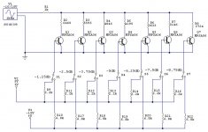
Referencing the attached schematic:
Switching the bjt's with +5V (as from a microcontroller) will pull the shunt resistors to ground. Each consecutive resistor from left to right is added to the previous (I have a spreadsheet to calculate values if anyone is interested). The -15V supply turns the bjt switches completely off (should be higher negative voltage than the highest negative-going signal excursion).
Simulations show low distortion and very little if any affect on bandwidth (ie capacitive loading).
I have no idea if this is Wayne's circuit or not, but it seems to work well, is cheap and easy to implement. I'm going to try it in a preamp soon.
I will be adding another ladder for the 10db steps, so I should have an attenuator with a range of -88.75db to 0db in 1.25db increments.
Anyone figure this out? I think I might have... Nelson?
Referencing the attached schematic:
Switching the bjt's with +5V (as from a microcontroller) will pull the shunt resistors to ground. Each consecutive resistor from left to right is added to the previous (I have a spreadsheet to calculate values if anyone is interested). The -15V supply turns the bjt switches completely off (should be higher negative voltage than the highest negative-going signal excursion).
Simulations show low distortion and very little if any affect on bandwidth (ie capacitive loading).
I have no idea if this is Wayne's circuit or not, but it seems to work well, is cheap and easy to implement. I'm going to try it in a preamp soon.
I will be adding another ladder for the 10db steps, so I should have an attenuator with a range of -88.75db to 0db in 1.25db increments.
Attachments
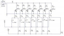
a better arrangement
This switching arrangement should work better. Think of the switches as active PNP elements pulling up to 5V, and the 15V pull-downs will work when they are in a floating state. I think this should work straight from a microcontroller, but would have to test the idea.
This switching arrangement should work better. Think of the switches as active PNP elements pulling up to 5V, and the 15V pull-downs will work when they are in a floating state. I think this should work straight from a microcontroller, but would have to test the idea.
Attachments
Zen Mod said:I know at least from pro mixing desks that I can hear total silence ....
Zdavro !
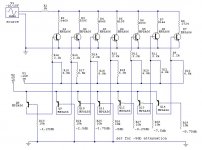
On mixing desks, we often use VCA. They're not the same thing. Attached picture is VCA create by one of our member.
Attachments
AudioFreak said:Certainly works for balanced signals but you will likely find that you can never get total silence using this method.
Expectations for a volume control don't usually go below about
-60 dB. When you go below -60 or -70 dB, you can just mute the
circuit.
😎
MaxS said:Attached picture is VCA create by one of our member.
Khm, as much as I'm flattered by the attention my little picture is receiving here, the credit is due elsewhere I'm afraid. I did not design the VCA in question. It is part of the old and famous UREI 1176 fet-based compressor (cloned and heavily modded by yours truly). More importantly, the VCA is not suitable for wide-range volume control applications. For this purpose, THAT 218x ICs may be a better solution, which is also used by many professional console manufacturers.
Regards,
Milan
Re: Anyone figure this out yet?
Is your technique similar to Wayne’s? I rather doubt it for several reasons. You will need some kind of buffer between your two proposed ladders if they are both to operate at a virtual earth point. The Pass pre-amps have a single gain stage which would preclude this arrangement. I suppose this problem could be overcome by using a single ladder and extending the number of ‘switches’ to match the desired number of attenuation steps but that would require a significant amount of components! Anyone already tried this out?
The other reason I suspect your approach is not the one used in the Pass pre-amps, is that in order to stand any chance of obtaining a patent, a circuit needs to be both sufficiently novel and non-obvious. No offence, but I don’t think your approach meets these criteria although I am no expert.
Anyway, the approach doesn’t have to be the same as Wayne’s to be useful. Personally I am more interested in how to build an attenuator with similar benefits to those claimed by Wayne’s arrangement rather than necessarily coming up with something similar in execution. Always assuming that it is possible of course 🙂
Looks good and I see no reason why it shouldn’t work well. However, I’m curious as to why you have opted for a parallel arrangement for increasing attenuation values rather than individual, i.e. so that there is only one resistor to ground at any given setting. What do you see as the advantage? I suppose it may increase the headroom by reducing the signal level that the attenuator typically sees. Then again it will be more difficult to arrange for precise attenuation values due to resistor tolerances as the number of parallel resistors increases. There is also the potential issue of more base current flowing to earth at values of attenuation where several ‘switches’ are on, but I’m not sure whether this is of practical significance. Personally I’m more inclined to the topology suggested by both maik and Dave earlier in this thread (posts #58 and #59).nobody special said:Anyone figure this out? I think I might have... Nelson?
I have no idea if this is Wayne's circuit or not, but it seems to work well, is cheap and easy to implement. I'm going to try it in a preamp soon.
Is your technique similar to Wayne’s? I rather doubt it for several reasons. You will need some kind of buffer between your two proposed ladders if they are both to operate at a virtual earth point. The Pass pre-amps have a single gain stage which would preclude this arrangement. I suppose this problem could be overcome by using a single ladder and extending the number of ‘switches’ to match the desired number of attenuation steps but that would require a significant amount of components! Anyone already tried this out?
The other reason I suspect your approach is not the one used in the Pass pre-amps, is that in order to stand any chance of obtaining a patent, a circuit needs to be both sufficiently novel and non-obvious. No offence, but I don’t think your approach meets these criteria although I am no expert.
Anyway, the approach doesn’t have to be the same as Wayne’s to be useful. Personally I am more interested in how to build an attenuator with similar benefits to those claimed by Wayne’s arrangement rather than necessarily coming up with something similar in execution. Always assuming that it is possible of course 🙂
Not much of a challenge since anyone who wants to can take
one apart. Of course you might have to buy one to do
it. Also, it's all SMT so get yourself a microscope.
My hifi budget is currently low, there is no special offer? 😀
I read and tried to understand the Susy patent.
But I'm afraid I got more questions than answers...

As already pointed out by others, the volume control could be made by changing the gain.
(Numbers refering to the picture on first page in the patent)
It is mentioned that R40 controls the gain. But is this the only part that sets the gain?
What happens is the ratios of R36/R22 and R37/R23 are changed? The gain also changes? Could this be the Wayne solution?
In the full patent text it says that the gates of 20 and 21 are at ground potential.
Unfortunately I didn't fully understood the use of R42 and R43, patent says there are in place to make the amp stable.
You can have DC current thru them.
But no gain settings here?
Anyone who has figured out how it works?
And an extra question....
Looked at the X-preamps documentation at passlabs.
Why does X0.2 has much better CMRR than the rest of the X's if it uses same solution?
- Status
- Not open for further replies.
- Home
- Amplifiers
- Pass Labs
- Technique behind Aleph X0.2 Volume Control