I have a Technics Quartz turntable that will start spinning the moment it's switched on. It will stop if I keep the start/stop button pressed but the moment I release it, it start spinning again.
For the studio it was used in, it had an external trigger/fader module fitted that I removed but the only mods I found so far was to route orange/yellow cable from the switch through the external PCB and +5V was stolen from Q201.
It gets up to speed very quickly, 33/45 works (needs a bit harder push sometimes), the brake works and pitch control works too.
Attachments

Last edited:
You do not say which model. I had a similar issue with a SL D202 I picked up cheap from a car boot sale.
There are a bunch of Technics DDs eg SL D202, SL Q202 that have an instruction to rotate the platter manually by hand about 10 times after maintenance to re-engage the automatic functions.
This is easy to do so would suggest trying that first.
There are a bunch of Technics DDs eg SL D202, SL Q202 that have an instruction to rotate the platter manually by hand about 10 times after maintenance to re-engage the automatic functions.
This is easy to do so would suggest trying that first.
SP-25, just the motor. What would make it spin right after turning the main power switch on? Start/stop button has been checked, it doesn't short.
As you say -"no short in the on/off switch " then logically a "run " connection is reaching the chip especially when you say holding down the switch stops it .
You either have a wiring problem or a component problem , IC201/Q201 should be checked .
You either have a wiring problem or a component problem , IC201/Q201 should be checked .
(I think) the start/stop switch on these should act as a pulse to start / stop the motor, it's not a latching engage/disengage switch.
I was wondering what could they've done to it to make it run from the moment mains is switched on.
I will check Q201 and whatever is underneath it.
I was wondering what could they've done to it to make it run from the moment mains is switched on.
I will check Q201 and whatever is underneath it.
Can someone give an advice on this?
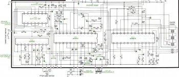
I've measured the voltage at TP23 and it was always at 9.18V (start condition calls for 7.5V or 0V for stop condition). Unsoldered one leg of R211 10k at the side of TP23, measured 4.6V and 4.55V on both legs of R211. With 1 leg unsoldered, the disc stays still and does not repond to S/S butto so the IC is not shorted.
I've measured the voltage at TP23 and it was always at 9.18V (start condition calls for 7.5V or 0V for stop condition). Unsoldered one leg of R211 10k at the side of TP23, measured 4.6V and 4.55V on both legs of R211. With 1 leg unsoldered, the disc stays still and does not repond to S/S butto so the IC is not shorted.
Attachments
Last edited:
The button looks OK (well, it either makes contact when pressed or is open).
I don't understand the 4V+ over R211 with 1 leg lifted or ~9.1V when the resistor is in circuit, where would that come from. There should be either 0 or 7.5V there.
I don't understand the 4V+ over R211 with 1 leg lifted or ~9.1V when the resistor is in circuit, where would that come from. There should be either 0 or 7.5V there.
Last edited:
Tried disconnecting both connectors, did nothing so at least we can exclude that.
Starting to suspect Q201 short.
Starting to suspect Q201 short.
I suspect the previous owner modified the logic control for the remote start function. Look for a pull-up or pull-down connection or resistor added by the previous owner that isn't consistent with the schematic. You may find an added link or resistor on the PCB that needs to be removed, or possibly a missing component that needs to be added back.
I managed to find a picture of what looks like a vanilla SP-25 PCB and there is a resistor added between 2 legs on one of the IC's on my SP25, I'll have to look again tonight but I think it sits between pin 1 and pin 14 on IC302...but that would be R307 on the schematic??
I've also noticed the legs turning green on most electrolytics, replaced all but the main PSU cap which measured perfectly fine.
Strangely enough most caps still measured 'decent', except for 1-10uF values that were reaching 2.5 Ohm ESR.
I've also noticed the legs turning green on most electrolytics, replaced all but the main PSU cap which measured perfectly fine.
Strangely enough most caps still measured 'decent', except for 1-10uF values that were reaching 2.5 Ohm ESR.
Last edited:
Compared the pictures but it seems to be a JP model, slightly different. Removing the resistor did nothing.
Checked all transistors, no shorts.
Checked all transistors, no shorts.
TP23 will only be 0V while the start/stop button is held down.
If the turntable runs regardless of whether IC101 pin 6 (TP10) is 5V (run) or 6.6V (stop), then I suspect IC101 is faulty.
IC201 pin 13 (TP16) should be high (5V) when turntable is running and low (0.2V) when turntable is not runing. If pin 13 jumps back to high when you take your finger off the start/stop button, then I think the latch in IC201 isn't working.
If IC201 pin 13 is bi-stable when you push the start/stop (i.e. stays in the same state when you take you finger off the button and doesn't jump back) then IC201 is OK and something is wrong around R206 - R210 or C212 (leaky cap?).
That is not consistent with the schematic I have; the start/stop switch should take TP23 to ground when pressed.The TP23 is never 0 in mine, 9.19V, with button pressed - 9.18V.
Attachments
Last edited:
This I don't understand either, it should pull it to 0V but measuring at TP23 to ground I'm getting either ~9.19VDC or ~9.18VDC with the button pressed in. That doesn't make sense and 9V is like a full rail voltage of one of the rails.
That could be correct but why does the switch make the platter stop? I've measured the switch and redone the solder joints aswell.
Last edited:
- Home
- Source & Line
- Analogue Source
- Technics turntable keeps spinning