Clearly from your voltage reading something happens when you press the switch. However if the schematic I posted is correct, TP23 must drop to near 0V when the switch is pressed unless there is a fault with the switch, the PCB track or wiring to the switch, or with the actual ground continuity on the other side of the switch. If you have a clip lead try clipping between TP23 and a known good 0V ground, and see if this will stop the turntable motor.
Sorry, did not read all this again.That could be correct but why does the switch make the platter stop? ...
I think it's a bit more complex than that, though. 😕 I tried disconnecting the connector going to the switch and TP23 is always at ~9.2V. I'm puzzled as there are jumpers on the board marked "Only for DPxxx" and the SM doesn't say anything about these. I don't see any fresh solder on the jumpers or any resistors that don't match the original ones.Clearly from your voltage reading something happens when you press the switch. However if the schematic I posted is correct, TP23 must drop to near 0V when the switch is pressed unless there is a fault with the switch, the PCB track or wiring to the switch, or with the actual ground continuity on the other side of the switch. If you have a clip lead try clipping between TP23 and a known good 0V ground, and see if this will stop the turntable motor.
Last edited:
Haven't checked Q201, assumed a broken Q201 would cause unstable operation or runaway of the motor. Can I remove it without any damage and then measure TP23?
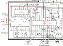
According to the schematic I have (see snip below) when you press the start/stop switch, TP23 is shorted to ground through the start/stop switch. This in turn takes IC201 start/stop input pin 19 to 0V, which is the signal to toggle the motor on or off.
Attachments
As seen before it is obvious that switch S310 momentarily working and
TP23 voltage always the same are conditions that exclude each other.
A possible quick fix for the main problem would be to rebuild S301 to or
replace it by a two position switch.
Remote possibility is S301 has contact bounce, in this case a small cap
across TP23 and ground could help.
Just for completeness, re Q201 you addressed possible failure in post 10
and before, but did not check it.
And it doesn't make any sense because no matter what, the voltage at TP23 is wrong in the first place (9.2 instead of 7.5V) but I will check Q201. If I understand the schematic correctly, 9.2V from the emitter of Q201 is correct.Yes, and it is irritating the he says T23 voltage stays the same.
Last edited:
How to treat your fellow DIYA forum members :
- type/model number belong in the first post and in the headline,
- if you own a manual or schematic post a link as early as post 1,
- a hint of your experience and abilities can be useful, we have
everything from the complete blind to rocket scientists here,
- it is also useful to know something about your equipment,
- if you receive specific requests to check or measure something
just do it or tell us why you do not (for instance "I do not own a
voltmeter").
Hope we agree.
... If I understand the schematic correctly, 9.2V from the emitter of Q201 is correct.
So why do you expect to see 7.5 V then ?
TP23 is directly connected to Pin 19 of IC201, that should be 7.5V or 0V.
9.2V on TP23 could mean TP23 is shorted to the output of Q201? There is just a 10k resistor inbetween.
9.2V on TP23 could mean TP23 is shorted to the output of Q201? There is just a 10k resistor inbetween.
Attachments
Last edited:
You need to fault find the start/stop switch ground problem first. Even if there are other faults, the turntable is not going to operate while the start/stop switch circuit is faulty.
You need to find out why the start/stop switch does not ground TP23 as expected. If the ground connection from the main PCB pin 3 to the switch PCB pin 3 is faulty preventing the start/stop switch function, then there is likely no reference for either 33 ⅓ or 45 rpm speed selection switched being supplied to IC201 either, i.e. neither of pin 6 or 7 of IC201 being grounded to set a speed. In that case, voltages around IC201 are quite likely meaningless.
You need to find out why the start/stop switch does not ground TP23 as expected. If the ground connection from the main PCB pin 3 to the switch PCB pin 3 is faulty preventing the start/stop switch function, then there is likely no reference for either 33 ⅓ or 45 rpm speed selection switched being supplied to IC201 either, i.e. neither of pin 6 or 7 of IC201 being grounded to set a speed. In that case, voltages around IC201 are quite likely meaningless.
Again, where did you get that "Pin 19 of IC201" should be at 7.5 V ?
This is an input pin and has no voltage of its own. So expect the same
voltage here as on TP23 and on Q201 emitter (as long as no current is
going through R211 with open switch).
You claim that push button S301 is working momentarily, but without
TP23 going to zero at the same time - this is not possible. Check again.
A last test proposed : what happens if you power up the tt with S301
pressed at the same time (procedure : tt is without mains power first)?
Let me add to post 31 : "Good pictures are always worthwhile and are
necessary in many cases".
Ok, fixed. 1 @#$%#$ jumper that was not mentioned in the manual was shorted...there are a few jumpers on the PCB marked "Only for DPxxx" that aren't in the service manual.
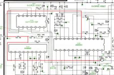
Now looking at the schematic it connects the base of Q202 to Pin 19 of IC201. They must've soldered it from the top as the solder joints at the bottom looked factory which threw me off.
Not much info on the DP numbers, except for this AK thread: Technics Turntable Noise, can you help diagnose? | Page 3 | Audiokarma Home Audio Stereo Discussion Forums
Last edited:

- Home
- Source & Line
- Analogue Source
- Technics turntable keeps spinning