Latest update with questions. Got and installed the Q705, used a 2SC3940A-R. The R version has different 1hfe rankings, so hope this is not an issue. Had a small error in the first soldering, started to see it heat up after about 10 seconds, shut down and investigated. Input voltage strong at 14.5 volts, output only 3, not 6.8. Found a bad solder, repaired, and display back on. Voltage of the collector high by 1/2 volt 7.3 instead of 6.8. Emitter voltage high by 1 volt, 7.2 vs 6.2. Interesting the collector is higher than the emitter. Checked all components in the system and they appear good and in range except maybe the other transistor Q722. Found 5 volts at the collector pin instead of .5 volts. I attached the mini circuit below. All the resistors and diodes test fine, but maybe not the resistance of Q722, which has 10k of series resistance internally in series with the collector of Q722. I can't measure this, but my best guess is that this is the reason why the collector voltage is 5 vs .5, which would then affect the C&E voltages of Q705. Q722 is a UN4215. Could I be right? Can anybody input an opinion. Bj


Last edited:
Did you ever find the root cause my SU-G75 went down last weekend and same situation that you decribed….everything works hooked up except the amplifier? Bought new fuses but that didnt work? Im stumped….thanks RobertNo sound, no display
I have a similar problem with my SU-G75, but I am unable to find the root cause. There is no display and no sound but I hear a click from the relay when I press the power button.
You were talking about a Q705, but there is only Q701 and Q708 on my board.
Anyone have a solution or something to help me.
Thanks you!
Keep me posted because the same thing happened to my amplifier last weekend and ordered new fuses and it still didn’t work. Everything else on the stereo system is working fine. It clicks but nothing on the amplifier. Somehow it’s making connection and current to the other components, but nothing showing up on my amp SU – G 75. I’ll keep checking your outcome before I decide to take it in. Since I’m no electrical guru but a jack of all trades. 😉 thanks RobertLatest update with questions. Got and installed the Q705, used a 2SC3940A-R. The R version has different 1hfe rankings, so hope this is not an issue. Had a small error in the first soldering, started to see it heat up after about 10 seconds, shut down and investigated. Input voltage strong at 14.5 volts, output only 3, not 6.8. Found a bad solder, repaired, and display back on. Voltage of the collector high by 1/2 volt 7.3 instead of 6.8. Emitter voltage high by 1 volt, 7.2 vs 6.2. Interesting the collector is higher than the emitter. Checked all components in the system and they appear good and in range except maybe the other transistor Q722. Found 5 volts at the collector pin instead of .5 volts. I attached the mini circuit below. All the resistors and diodes test fine, but maybe not the resistance of Q722, which has 10k of series resistance internally in series with the collector of Q722. I can't measure this, but my best guess is that this is the reason why the collector voltage is 5 vs .5, which would then affect the C&E voltages of Q705. Q722 is a UN4215. Could I be right? Can anybody input an opinion. Bj
View attachment 1279658View attachment 1279660
One option, you can go to manuals.lib and look at the schematic. If the issue is of power to the display, AND if it is similar to the G90, then check the voltages of the collector and emitter of Q752. I have attached a pic. The emitter should have an E printed on the board adjacent. The collector is the one on the opposite end. I'm guessing you should see 14.5 volts on the collector and about 7 volts on the emitter. Q701 and Q708, may also get hot or have bad solders. There should be +14.5 volts on the emitter of Q701, and -14.5 volts on the emitter of Q708. Start there. You can just ground the negative probe to the phono ground or frame. Wrap your positive lead with shrink wrap or e-tape so only the very tip is exposed. DO NOT want the side of the probe or tip contacting anything else. See part of the schematic attached. BJ

Thank you for the info., forgot to mention earlier I have service manual on my unit that I located online last week. I will continue to trouble shoot it based on your recommendations.
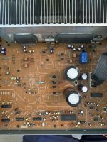
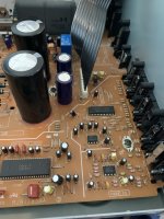
Q701 is at the top under the steel spring clamp. Start there to see if you have 14.5 v. I may have posted the wrong pic.
- Home
- Amplifiers
- Solid State
- Technics SU-G90 no display or sound