Hi
Got one of these power amps from Ebay. Relay pins have been bent so that it stays on. DC good at 6.5mv at speaker terminals on each side. Need an SSY69 relay but not available from main suppliers. I have a smaller sized relay G2R-2 24DC which I have used with other Technics amps. I could just solder some legs on to it and use it.
Any thoughts on why relay was forced - probably becuase it failed as opposed to DC?
I also have the matching pre amp / tuner STK808 but FM stereo will not work. Tried VCO and IF adjustment using service manual but no change. Could be a lot of things but have not tried cleaning switch yet.
Any advice appreciated
Last edited:
The contact points can get burn marks due to the arcing that occurs when the relay turns off when current is still flowing. When that has happened too many times, the contacts do not conduct any more.
The 5 A current rating of the G2R-2 24DC is OK but it might fail in 10-20 years. If that is a problem, use a relay rated at 8 A. Check the coils to have a similar resistance and voltage.
The 5 A current rating of the G2R-2 24DC is OK but it might fail in 10-20 years. If that is a problem, use a relay rated at 8 A. Check the coils to have a similar resistance and voltage.
Last edited:
Fault in protection circuit
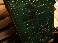
There are not many small caps in this amp so I may replace them. There is some failure in the protection circuit itself. Amp itself operates fine and DC low. There is an odd black wire under the circuit board. Not sure what it is for. Desoldered it and made no difference so put it back! Pic attached.
There are not many small caps in this amp so I may replace them. There is some failure in the protection circuit itself. Amp itself operates fine and DC low. There is an odd black wire under the circuit board. Not sure what it is for. Desoldered it and made no difference so put it back! Pic attached.
Attachments
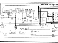
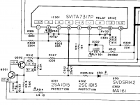
If no voltage at R310 there’s a hellatious dry joint or a break in the copper track
R310 connects the relay to +V (44V main feed) to the relay....
Pin 6 of IC301 straps relay to ground when all is well....
If all is well on one side of R310 should be +44V... other end of it 24V or so and relay will have 24V (R310 side) and side to IC301 pin 6 will be 0.6V or so.
If overload or DC detect fault, you would read 44V at all points of R310 and relay coill / pin 6 of IC301
Hi. Couldn't sleep so replying at 3am! What is that black wire on the back of the circuit board that I put a picture of above? Has that got anything to do with it in your opinion.
Am I checking voltage across the pins of the resistor or points before and after it? Apologies if this is a dumb question!
Am I checking voltage across the pins of the resistor or points before and after it? Apologies if this is a dumb question!
Yeah all voltages I look for are related to ground (unless stated otherwise)
Ok it’s in protect mode (either DC or overload detect)
What voltage at R129 and R130 (either side) to ground? If 5mv like you say, it must be overload circuit.
Check voltage of Collectors Q103 and Q104 (should be 37V)
Ok it’s in protect mode (either DC or overload detect)
What voltage at R129 and R130 (either side) to ground? If 5mv like you say, it must be overload circuit.
Check voltage of Collectors Q103 and Q104 (should be 37V)
Last edited:
Hi
Q103 and Q104 are both 39.1v at Collector.
R129 and R130 on both sides for each start at about -1v and then rapidly drop to -0.5v and then contines to drop slowly in mv stages.
I can check again tonight when I get back from work if needed.
Much appreciated. I really want to get this working as I have another one of these and want to use them as dual mono blocks.
Sweet.... rare to have a pair of these....
Let’s look into protect circuitry
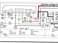
Q301 Q302 and IC301
Check Voltage at pin 1 of IC301 should be -0.7V
Then Q301 and Q302
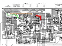
See schematic attached for correct voltages for operation.
Pin 6 will appear near on 44V as it is still in protect mode... we just need to see why it’s in protect...
- also on the side is the mono/stereo switch clean... may help w/ dc balance.
Let’s look into protect circuitry
Q301 Q302 and IC301
Check Voltage at pin 1 of IC301 should be -0.7V
Then Q301 and Q302
See schematic attached for correct voltages for operation.
Pin 6 will appear near on 44V as it is still in protect mode... we just need to see why it’s in protect...
- also on the side is the mono/stereo switch clean... may help w/ dc balance.
Attachments
Hi
Q301= 40v and Q302 =39.7v at collector.
IC301 - really hard to read voltages but... Scared of shorting it!
pin 1 = +0.5
pin 2 =-290mv and dropping
pin3 = -278mv and dropping
pin4 = -265mv and dropping
pin5 = -0.75v and dropping
pin6 = 43.7v stable
pin7= -270mv and dropping
pin8 = -270mv and dropping
pin9 = 2.1v and dropping
Hope this makes sense. If not will try again.
- Status
- This old topic is closed. If you want to reopen this topic, contact a moderator using the "Report Post" button.
- Home
- Amplifiers
- Chip Amps
- Technics SEA 808 Relay Equivalent