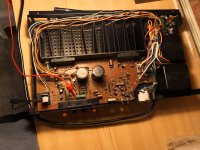
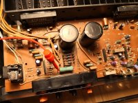
I’d check Q301 for shorts
Voltages should be
Q301 E 37.4 ... B 37.4 ... C -0.4
Q302 E -0.7 ... B -0.4 .... C 37.4
Your voltages mat be a little different... key is that Voltages of equal values are that still (like Q301 E & B)
——-
When overload protect kicks in it’ll pull up pin 1 of ic301 from -0.6V to +0.5V or so, turning off relay.
I don’t think it’s IC301 - went through a similar thing with some commercial amps
Do want to do a few tests...
1st I’d like to check overcurrent circuit
Desolder Q103 and Q104 - then run... if it comes out of protect, we need to investigate that area.
If not re install
Then DC detect - using 2 resistors (around 20 ohm) strap pin 2 and pin 3 to ground with these... if it comes out of protect, it’ll be DC detect causing this.
On the side does power indicator led operate?
Hi. Removed Q103 and Q104 and switched on. Still around 44v eveywhere around coloured protect circuit as shown in earlier post when testing to ground.
Power LED operates.
"Then DC detect - using 2 resistors (around 20 ohm) strap pin 2 and pin 3 to ground with these... if it comes out of protect, it’ll be DC detect causing this."
Just to clarify you are talking about the pins on IC301. So do I attach or solder a resistor to each of those pins at one end and a wire to ground at the other end and switch on? Do I need to have both resistors to ground at the same time then check voltages? I will have to look around for suitable resistors or order some. What range of Ohms of the resistor would be acceptable from 20 Ohms? Hope this makes sense!
Last edited:
Yeah IC301
Yes you got it 1 resistor from pin 2 to ground - and one from 3 to ground.... then fire up
If resistors can’t be found - just use wire - won’t harm anything.
If it comes out of protect - remove one wire and retry And vice versa - to see if it’s left or right channel triggering
Yes you got it 1 resistor from pin 2 to ground - and one from 3 to ground.... then fire up
If resistors can’t be found - just use wire - won’t harm anything.
If it comes out of protect - remove one wire and retry And vice versa - to see if it’s left or right channel triggering
Hi
Pin 2 to ground increases voltage on protection circuit (green area on diagram) from 43.4v to 45.5v. I did not use a resistor.
Continuity from pin 4 to ground = 390mv this time
Let me know if you want me to measue anything again.
I tested Q103 and Q104 using my transistor tester and both were good.
Pin 2 to ground increases voltage on protection circuit (green area on diagram) from 43.4v to 45.5v. I did not use a resistor.
Continuity from pin 4 to ground = 390mv this time
Let me know if you want me to measue anything again.
I tested Q103 and Q104 using my transistor tester and both were good.
C302 was 2.8V? Should be -V
D301 half wave rectifies transformers output to -V (-15 sounds plausible)
If R305 is open it could be a culprit
I’d expect -3V or more
Id check good amp voltage at those points.
If C302 is shot it won’t sustain -V
It’s a balancing act for Pin 1 of IC301..... AC feed (D301 C302) pulls to -V influence
On the other side there’s R307 fed from +V that will nearly pull up voltage
The balance is from Q302, on overload, it too feeds +V toward to pin 1 which will have it go from -1v to More Than 0V (0.2V or higher) which will trip relay out
When amp is turned off, the AC feed stops feeding the -V feed to pin 1, and the +V (stored in main caps) pulls up pin 1 quick, to disconnect relay (no power off noise)
Last edited:
- Status
- This old topic is closed. If you want to reopen this topic, contact a moderator using the "Report Post" button.
- Home
- Amplifiers
- Chip Amps
- Technics SEA 808 Relay Equivalent

