jneutron said:[snip]You ask very relevant question, Jan....but statements such as .1dB (so what) are indicative that you (as you stated up front) do not understand the ramifications of localization and soundstage simulation[snip]Cheers, John
Sometimes that is the only way to get ANY reaction.
BTW, on the 10 or 15 or whatever nH per foot of your cable, how does that compare as far as impact on localisation, if we figure in an amplifier output inductor of, say, 5uH, (or 3uH, or 6uH, or one channel 20% higher than the other). Anyway, you get the point, I guess.
Jan Didden
soongsc said:Gee John!
In the beginning I thought you did not agree "skin effect" exists. Now I'm getting the feeling that you agree that there is skin effect, but the other sources did not explain it in the correct manner. It this understanding correct?
My apologies for any misunderstanding..
Skin effect is real. It is the conductors response to the internal time varying magnetic field that is caused by a time varying current.
The only issue I have is that skin effect has been taught to the masses of engineers and physicists as being exactly like the effect caused by a propagating TEM (Transverse Electric Magnetic wave) attempting to drive into the surface of the metal.
As such, it provides an incorrect visualization of the actual internal mechanism, and provides no insight as to what actually occurs for stranded wires, rectangular wires, jelly roll capacitors, ribbbon wire pairs, ribbon inductors, and even steel core wires. It also provides an incorrect visualization of "strand jumping", as poor strand to strand conductivity does not cause more skinning...but, less.
Hawksford used the old exponential calculation method, and as a result, missed the internal 30 nH inductive component of his parallel wire test..
Effect overall on sound via ITD and IID?...no gotsa clue..yet.
Cheers, John
From me?...Naaaah..janneman said:Sometimes that is the only way to get ANY reaction.

janneman said:
BTW, on the 10 or 15 or whatever nH per foot of your cable, how does that compare as far as impact on localisation, if we figure in an amplifier output inductor of, say, 5uH, (or 3uH, or 6uH, or one channel 20% higher than the other). Anyway, you get the point, I guess.
Jan Didden
Yup, I get the point..
I've no idea how the lumped inductance vs distributed inductance/capacitance could possibly have an effect...
In fact, I've no idea why a cable with a total of say 100 nH of inductance could make a difference that is audible when compared to one with 250 nH, when the terminals are binding posts, and the one inch distance causes approximately 29 nH per post pair, both at the amp and at the speaker (assumed copper posts)...even if I dressed the wires correctly, your still talking 60 nH of unexpected inductance.
But then again, a zip cord has about 200 nH per foot, or 2000 nH total, with 60 at the ends...
Answer...unknown..but that is of course, why I am working the audibility end...if we lower the limits of acceptible response to what is actually required for localization to a foot, or six inches, then perhaps these questions will be answered to everybody's satisfaction...is .03 dB interchannel accuracy really needed as well as 2 to 5 uSec interchannel???? Or, are there human localization restrictions that allow loosening of those numbers?
I don't even understand why woofer litz wires are put so far apart..that loop not only increases inductance, but it's moving in a magnetic field, and is perfectly poised to pickup second harmonics from the iron saturation characteristics..(no shorting coil).
Cheers, John
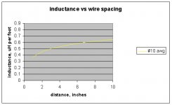
PS..OOOOH , almost forgot this pic:btw, x axis is distance between conductors...I approximated a binding post as a #10 wire..
Attachments
jneutron said:
My apologies for any misunderstanding..
Skin effect is real. It is the conductors response to the internal time varying magnetic field that is caused by a time varying current.
The only issue I have is that skin effect has been taught to the masses of engineers and physicists as being exactly like the effect caused by a propagating TEM (Transverse Electric Magnetic wave) attempting to drive into the surface of the metal.
As such, it provides an incorrect visualization of the actual internal mechanism, and provides no insight as to what actually occurs for stranded wires, rectangular wires, jelly roll capacitors, ribbbon wire pairs, ribbon inductors, and even steel core wires. It also provides an incorrect visualization of "strand jumping", as poor strand to strand conductivity does not cause more skinning...but, less.
Hawksford used the old exponential calculation method, and as a result, missed the internal 30 nH inductive component of his parallel wire test..
Effect overall on sound via ITD and IID?...no gotsa clue..yet.
Cheers, John
I recall somewhat that when we were studying magnetic brakes, the conductor plate thickness does have effect on eddy currents and how effecient the brakes were up to a certain point. So it just seems that the calculation of the depth at different frequencies has no clear cut definition, or there is a different way of calulating it that yield different results?
jneutron said:
From me?...Naaaah..
Yup, I get the point..
I've no idea how the lumped inductance vs distributed inductance/capacitance could possibly have an effect...
Cheers, John
PS..OOOOH , almost forgot this pic:btw, x axis is distance between conductors...I approximated a binding post as a #10 wire..
I think if you include an R with L & C, and do a SPICE simulation, the difference between lumped and distributed would show up. But then we would get into the issue about how distributed do you need to get for the simulated results match test results.
soongsc said:
I think if you include an R with L & C, and do a SPICE simulation, the difference between lumped and distributed would show up. But then we would get into the issue about how distributed do you need to get for the simulated results match test results.
Jan also is giving an example of an output inductor in parallel with a low value resistor..for my tigers, it was 10 ohms and some indeterminate number of turns around an electrolytic cap body, of all things..😕
If you wish to determine how fine the distribution of L, C, and R need to be to model reality, just keep increasing the fineness of the elements..start with 10, work your way up to a thousand or ten thousand...the output will asymptotically approach a continuous distribution. That size model is probably beyond a spice program, perhaps you should just write the analytical equations for an element, and some VB code to set the number of elements and their size?.
Lenz's law states that the eddy currents within the plates, ala magnetic brakes, will be generated in such a way as to attempt to exclude an increase in the magnetic field within the plate, so I could easily see how plate thickness increase starts to see diminishing returns (specially since you already stated such🙄 ). (no free lunch)
Cheers, John
jneutron said:
Jan also is giving an example of an output inductor in parallel with a low value resistor..for my tigers, it was 10 ohms and some indeterminate number of turns around an electrolytic cap body, of all things..😕
If you wish to determine how fine the distribution of L, C, and R need to be to model reality, just keep increasing the fineness of the elements..start with 10, work your way up to a thousand or ten thousand...the output will asymptotically approach a continuous distribution. That size model is probably beyond a spice program, perhaps you should just write the analytical equations for an element, and some VB code to set the number of elements and their size?.
Lenz's law states that the eddy currents within the plates, ala magnetic brakes, will be generated in such a way as to attempt to exclude an increase in the magnetic field within the plate, so I could easily see how plate thickness increase starts to see diminishing returns (specially since you already stated such🙄 ). (no free lunch)
Cheers, John
Inductor around a cap is definitely not for the weak minded.
 Especially if you don't know the structure within the CAP and whether the currents are in the same direction or opposite.
I just mentioned SPICE as an easy means of understanding the difference between distributed and lumped. Of course for someone like you that can speak in code faster, it is a gift.
soongsc said:
Inductor around a cap is definitely not for the weak minded.
For spice, I was thinking just of lots and lots of series R and L, with shunt C's..the old classic transmission line model without the G of the dielectric..
soongsc said:
I just mentioned SPICE as an easy means of understanding the difference between distributed and lumped. Of course for someone like you that can speak in code faster, it is a gift.
Ummm, not exactly...notice I did not volunteer to do it??
I can visualize a simple way to model a coaxial run, with either braid inner or solid inner. Braid is a no brainer, as no skin effect occurs...a solid would be much more fun, as the leading edge of a step function signal will require differential elements with depth modelling of the conductor as well as the dielectric, and running the problem through time...I would think that would take a coupla man-months...so, I punt..
 😀
😀 Other wire geometries tend to be a tad more complex to model, so I put my head in the sand for those..
For skin, the best effort is spent on simple cross sections.
Cheers, John
soongsc said:Inductor around a cap is definitely not for the weak minded.
Ah, just realized you meant around the "electrolytic cap", not the coaxial capacitance of a transmission line feeding the inner conductor normal to the surface..
Yes, a large electro is typically made by rolling a foil pair.
It is how the leads are connected that determine the distributive inductance that can starve the dielectric..
Connect both leads at one end of the foil construction, and that is the best way..
Connect one lead at the center of the roll and the other at the outer end, and the currents within each foil are in the same direction..this is a solenoid field producer, like a foil inductor. At frequency, this causes the current to starve from the middle of the cylinder and concentrate closer to the ends..
Lots of caps will have the lead connection point dependent on the end can spacing..in these cases, the roll between the lead connection points are a solenoidal inductor, while the foils outside of the outermost lead are "bifilar".
So, take a large electro, and wind a coupled solenoid inductor outside of it...then, connect that coupled inductor in series with the output....good thinking...(what were they thinking)😕 😕 😕
Cheers, John
Could anyone explain to me how and why Inductance and Capacitance affect loudspeaker wire performance?
keyser said:Could anyone explain to me how and why Inductance and Capacitance affect loudspeaker wire performance?
Look..we're way too busy tossing big, technical sounding, mutisyllabic words to waste any time answering questions related to the topic of the thread...whaddya think we are??😉 😉 😉
They both slow the line down, they both store energy and deliver it slightly behind in time, they can affect the wire and speaker frequency response..
Both are bad, less is better..
Physics says L times C will be a constant depending on the conductor and the insulator..
Making sqr (L/C) equal 8 for an 8 ohm load minimizes all the bad stuff.
And, it is not clear from a scientific point of view, why the very small effects of L and C SHOULD make an audible difference. Current understanding of what we are sensitive to with stereo, does not explain why it would..I believe current understanding is, umm, incomplete..
That, in a nutshell, is the reason for all those multi-syllabic words..
I hope that helped..

Cheers, John
jneutron said:
Both are bad, less is better..
Physics says L times C will be a constant depending on the conductor and the insulator..
Making sqr (L/C) equal 8 for an 8 ohm load minimizes all the bad stuff.
I hope that helped..
Cheers, John
Less is better if sqr (L/C) matches 8 ohm or whatever the speaker impedance is, hoping that its constant.
😀
The Ultimate Monitor displays a curve that looks quite good. My designs mostly look like that currently.
Thanks.. I did actually try to work my way through this thread, but I sort of lost track half way the first page!Look..we're way too busy tossing big, technical sounding, mutisyllabic words to waste any time answering questions related to the topic of the thread...whaddya think we are??
ok... interesting...Physics says L times C will be a constant depending on the conductor and the insulator..
you want to keep both as low as possible.😕 😕
we have names and numbers to quantify both L and C. Do we also have figures to qualify them? Which of the two has to me lower?
keyser said:
Thanks.. I did actually try to work my way through this thread, but I sort of lost track half way the first page!
To the layman, this stuff looks like just so much drivel..dry, boring...hogwash...the attempt at reading through this is appreciated, thanks..your questions are very appropriate, and the reality is how does it affect the bottom line...
It is exactly the same situation I encountered at my current job...it took about a year and a half before I understood what they were talking about..
 😕😕
😕😕 keyser said:
ok... interesting...
you want to keep both as low as possible.😕 😕
we have names and numbers to quantify both L and C. Do we also have figures to qualify them? Which of the two has to me lower?
It is a balance between the two..in theory, for the least storage energy, the equation Z = sqr(L/C) should be used. that means, for an 8 ohm load, L/C should be =64..
For my first build, L was 10 nH, C was 288 pF..units are important, so convert the inductance from uH to pH..
10 nH = 10,000 pH.
10,000/288 = 34.7 the square root of 34.7 is 5.89...that is my cable Z.
I would think it is important to get close, but how close is not set into cement..there is no correlation data to support this stuff yet.
Cheers, John
jneutron said:
For my first build, L was 10 nH, C was 288 pF..units are important, so convert the inductance from uH to pH..
10 nH = 10,000 pH.
10,000/288 = 34.7 the square root of 34.7 is 5.89...that is my cable Z.
I would think it is important to get close, but how close is not set into cement..there is no correlation data to support this stuff yet.
Cheers, John
If you measure L and C those are the lump numbers, since we know that distributed and lumped L/C react differently, how can we relay on measured data unless we know the relationship between the distributed value and the lump value? Especially C
soongsc said:
If you measure L and C those are the lump numbers, since we know that distributed and lumped L/C react differently, how can we relay on measured data unless we know the relationship between the distributed value and the lump value? Especially C
A reasonable question.
The test equipment for measurement of L and C are capable of distinguishing L and C independently of the other parameter.
It is while driving the low impedance load that the storage really comes into play...the meters never push the wire hard when measuring L and C.
Cheers, John
soongsc said:
From the abstract, it deals with high frequency..note the statements Time Domain Reflectometry and Time Domain Transmission measurements.
What strikes me as interesting is his useage of the phrase ""The model shows excellent agreement with experimental....."", as it makes it seem that TDR and TDT are "new"..
They are over 20 years old, so why "experimental".
Back to the subject...The old exponential penetration equations are good for DC, and for high frequency regions of "skin effect"..
The transition regime between, smack into the audio band, are not addressed by this paper..
Oh well...thanks for bringing it up..
Hey, you said foil inductors were "more coherent"...have you any inductance measurements comparing regular air core units vs foil? I ask, as skinning in the foil ones should show at higher frequencies, the foil ones should drop in inductance..
Cheers, John
I was asking whether anyone had read it or not because it seemed like $15 or something to get it and I didn't know whether it was good or not.
Recently I also came across some speaker cable comparison reports that also used SPICE to do some modeling of the cables, but they just looks a bit not detailed enough. So I'm still researching whether there is any way to model the cables properly in SPICE.
With the foil inductors I just happed to give them a test when I was designing crossovers. The base just never sounded right compared with other parts of the music. So I put in foil inductors replacing the straight wire inductors, and I never when back. The values were both of 2mH, the difference in series resistance is about 0.2 ohm (foil is less), but I just did some calculation and it seems the gauge sizes are different, so I will have to go back and use a same gauge size foil inductor to have an accurate comparison.
The biggest difference is noticeable when listening to piano and Taiko drums. With the Taiku drums, you get a good feel of the initial impact and the following wave front after the hammer (or whatever you should call it) leaves the drum. With the piano, you just get a feeling that the highs and lows come from the same piano. I've listened to many systems, and somehow the piano just doesn't come out right. It's really hard to explain.
My philosophy is, if I'm not satisfied with the sound, I try to technically see if there is anything within my power to do to improve it, I try it, and if the results are what I expect, then I'm happy.
Somepeople may get stuck on what they like, which could be different from what is closer to the real thing. So whenever I listen, this is also somthing I try to consider. Who knows, I might start working on drivers some day.
I was talking with an owner of a hifi store one day, he mentioned that he had designed the ultimate interconnect many years ago, when I asked him what his theory was, he just said it was too dangerous to do it gain, and said nothing more. I later found out he used mercury. No wonder he wouln't tell me!
- Status
- Not open for further replies.
- Home
- General Interest
- Everything Else
- Technical discussion on loudspeaker cable