I've had a look at various websites and fora (inc. the quarter-wave site you linked) re: simulating the line and downloaded a few programs but thus far can't make head nor tail of it. The Mathcad/MJK stuff also appears to be defunct, or have I missed something?
If you have (the relevant version of?) the proprietary mathcad software the author may give it to you if you ask. He stopped making it freely available but both the author and the software are still around.
Getting up to speed with one of the currently available simulators may be a better option though. Hornresp gets mentioned a fair bit but there are others. I haven't used any of them to design a transmission line speaker and so am not in a position to make a strong recommendation.
Anyway, I'll have to do a LOT more reading on this stuff. Am I incorrect in thinking that most are made for you to work from having a driver and a 'goal' with regards to frequency response, rather than reverse engineering a cabinet and trying out different drivers within it?
The objective to reverse engineer an existing line to help find drivers with a satisfactory set of parameters is slightly different but I don't think it influences the suitability of the software significantly. You would run simulations while fiddling with the value of parameters to draw out what you want to know in pretty much the same way.
Not sure how I'm going to measure the interior bits of the line... Or am I misunderstanding/going about this the wrong way?
I haven't considered the problem in depth so take this as pointers rather than a recipe. You will need to determine the length and cross section of the line, the relative amounts of stuffing along the line (later measurements vs simulations should establish level of absorption) and the driver parameters. This should enable you to perform simulations. Measurements of what is coming out of the port and the drivers will then give you something to work with to determine the performance of your line.
Even though you have the parameters of your existing drivers in the spreadsheet I would be wary of them. Manufacturing tolerances can be large plus drivers change with age as bits harden, weaken, sag, corrode, dry out, etc... Measuring them may be worthwhile.
Once you have established the performance of your line then you can use the simulations to find reasonable sets of parameters and which current drivers might be suitable.
I'd assumed that apart from impedance they'd be pretty similar T/S-wise to the original ELAC 8DC/472 Studio 3 (v3) drivers (for which the spreadsheet has basically no T/S info). But comparing the incomplete data from the Studio 2 and 3 V2 drivers I'm not sure how similar I can assume the parameters of the 471 and 472 drivers will be?
Did the cabinet/line change between series 2 and 3 or just the drivers? If just the drivers then you can use the TS parameters from series 2 or 3 as a guide.
If you measure the parameters of the drivers you currently possess and get the simulations and measurements to match then there is little need for the information in the spreadsheet. In fact, if the simulations and measurements match well using the driver parameters in the spreadsheet there may be less need to measure the driver parameters. Measuring the driver parameters would be safer though.
TurtleRecall - how have you got on with this project? I have a long term project running on a pair of the Mk2's - yours look like the Mk3's. Also had the same issue as you regarding finding any replacement drivers - I have tried a couple but the parameters were not close enough and although I got them sounding ok, they were not really what I wanted to achieve.
On hold for now, Thetall. Despite the very helpful advice provided on this thread I'm no closer to understanding how to work out the horn's properties or put these into a program to determine the appropriate drivers.
Whatever drivers I go for, I'll need four of them (plus two tweeters), so would rather be absolutely certain that they'll definitely be the correct ones, as it looks like most drivers will require the cabs to be modified in some way, plus of course the considerable cost involved...
Which drivers did you try? Were you able to determine the ideal T/S parameters for the cabs? Are the Mk2 the 4 bolt drivers?
Sorry for the delayed response. Yes, they are the 4 bolt woofers. The ideal parameters must be similar to those used in the original design? Qm-1.77 Qe-0.77 Qt-0.50 VAS-50 Fs-31 Sensitivity 84.5
I tried a couple of old Kef 16 Ohm units and a pair of Monacor twin coil drivers but neither of these sounded right, even with tweaking of the crossover. I'm currently still persevering with the original drivers which aren't too bad after rotating a couple of them.
The main problem is that hardly any manufacturers make 16/15 Ohm drivers now. I have wondered if using lower Impedence drivers could work but obviously the crossover might need changing drastically and this could end up a waste of time too. It's a tricky one.
Cabinet plans
Good day all,
Almost 4 years after the fact, I resurrect this thread... 🙂
I have a pair of TDL-404's (Made in South Africa). Apparently one of the distributors here bought up most of the driver stock when TDL went out of business and built these into a ported enclosure.
But I would really like to rebuild these into their original and intended TL enclosures; problem is, I cannot find any information on the inside layout and measurements of the TL itself.
Can anyone help?
Thank you,
Jaco
Last edited:
I looked up the original ELAC drivers up in Falcon Acoustic's database, and the woofers were 16ohm 6" bextrene (Cobex..) drivers with a Qts around 0.5. That says closed box to me, but more thunderous transmission line box diagrams are easily found with google images.
Later ones might be Audax basses. IDK. Wealth of crossover data in this thread. Be worth investigating various designs if you are keen.
Later ones might be Audax basses. IDK. Wealth of crossover data in this thread. Be worth investigating various designs if you are keen.
Thank you for the response, and yes, these are ELAC drivers, same as used in the Studio 3/ii, but they are 210mm/8" drivers.
I also found that sealed cabinets will work better and will probably be going this route. It may also help with woofer "dampening", as I found that older Amps with poor damping factors struggle to keep up at high volumes.
Your thoughts?
I also found that sealed cabinets will work better and will probably be going this route. It may also help with woofer "dampening", as I found that older Amps with poor damping factors struggle to keep up at high volumes.
Your thoughts?
Yes, I slipped up there... 8" Elac 8DC/441 seems to be the woofers... but no matter. 🙂
I have a bit of a formula for unknown 8" basses:
https://www.diyaudio.com/forums/multi-way/203461-restoring-monitor-audio-r300-bookshelf-speakers-4.html#post4990630
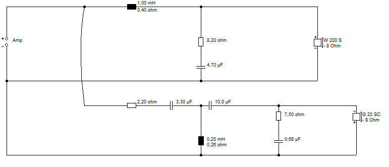
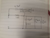
This is a KEF/BBC idea. The tweeter is reverse polarity around 3kHz. This corrects the approx 5cm (half wavelength) time alignment error with the bass. The 8.2R plus 4.7uF is just a bit of impedance correction. The bass uses it's natural 3kHz rolloff to a large extent.
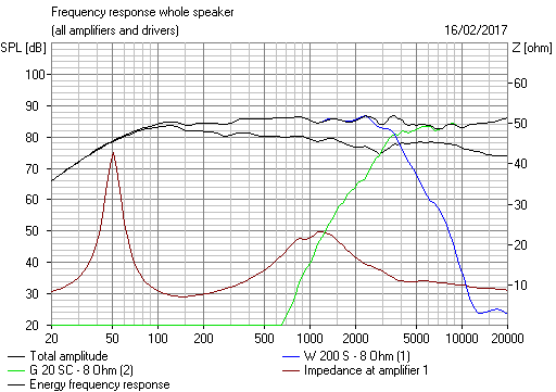
The bass coil is adjustable. 1mH gives a tight slamming sound, 1.8mH gives a deeper bass that is to some people's taste. I model them with Visaton software to see what goes on.
Software | Visaton
The basses wired in parallel won't affect things much. It's the idea that counts. All is adjustable in DIY. I am careful to keep the impedance above about 6 ohms and amp-friendly.
Hope that helps a bit. Not a difficult speaker IMO.
I have a bit of a formula for unknown 8" basses:
https://www.diyaudio.com/forums/multi-way/203461-restoring-monitor-audio-r300-bookshelf-speakers-4.html#post4990630
This is a KEF/BBC idea. The tweeter is reverse polarity around 3kHz. This corrects the approx 5cm (half wavelength) time alignment error with the bass. The 8.2R plus 4.7uF is just a bit of impedance correction. The bass uses it's natural 3kHz rolloff to a large extent.
The bass coil is adjustable. 1mH gives a tight slamming sound, 1.8mH gives a deeper bass that is to some people's taste. I model them with Visaton software to see what goes on.
Software | Visaton
The basses wired in parallel won't affect things much. It's the idea that counts. All is adjustable in DIY. I am careful to keep the impedance above about 6 ohms and amp-friendly.
Hope that helps a bit. Not a difficult speaker IMO.
This is good information, thank you Steve.
I already have an enclosure in mind, using the Golden Ration as close as possible. 🙂
But as a starting point, I am going to close off the ports on the existing cabinet just to get a "feel" for the potential sound. It is currently around 100 liter internal volume.
I already have an enclosure in mind, using the Golden Ration as close as possible. 🙂
But as a starting point, I am going to close off the ports on the existing cabinet just to get a "feel" for the potential sound. It is currently around 100 liter internal volume.
Morning Steve and Jaco
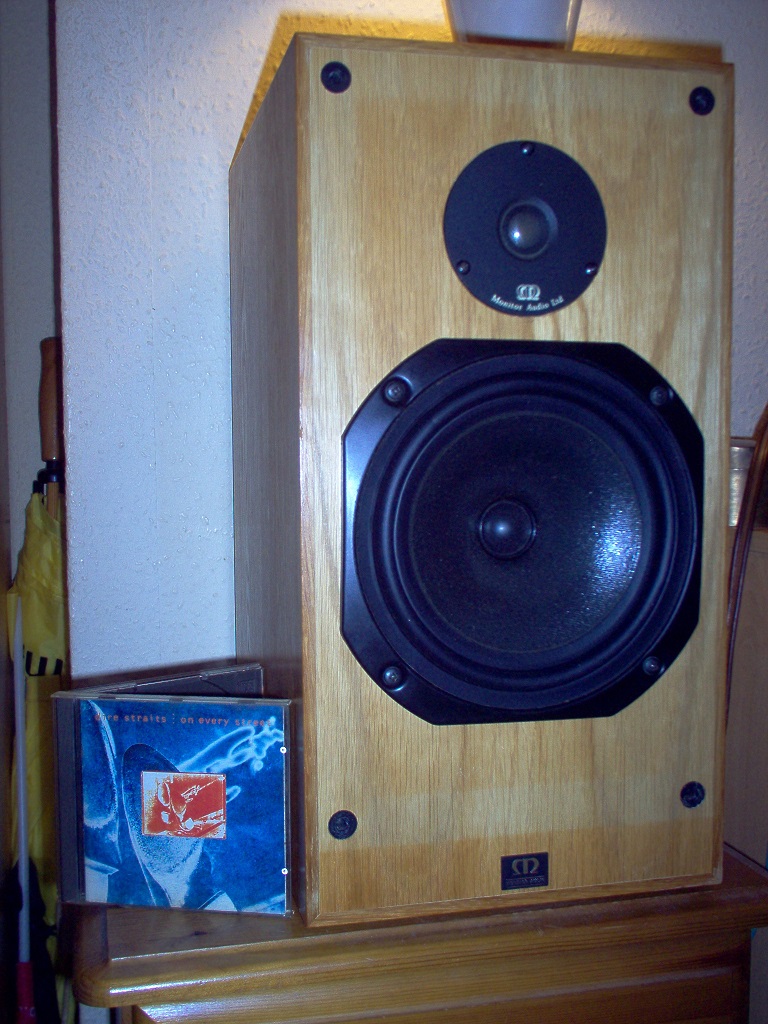
These 404's seem mighty odd to me having the appearance and size of the Studio 3's MKII bar the cabinet design. I've only recently become aware of the 101,202,303 and 404 series. I'd be interested in seeing a photo of the crossover to compare with the Studio 3's.
The 8DC441's definitely need a Zobel to tame the peaks in the upper mids - something in the region of a 5uF cap and 15 Ohm resistor.
They work very well in the Studio 3 cabinets as a TL but can't comment on how they work in the 404 cabinet as I've never heard them.
Cheers
Mark
Just to add, Jaco ..have you tried repositioning them? I know with the Studio 3's, if you get within 0.5m of walls, particularly the side walls, the sound esp bass, can change quite a bit (other room factors affecting too obviously). I have managed before to negate this by keep moving the speakers distance and tow-in a little at at time when space is limited but it's much easier if you can clear rear and side walls by over 0.5m.
Morning, closed box fans! 😎
Every closed box builders knows this formula by heart... or should... 😀
Vtc = Vas / ((Qtc ^ 2/Qts ^ 2) - 1)
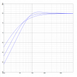
For Qtc = 0.7 and Qts = 0.5 it comes out at the Vas for maximally flat (orange) BW2.
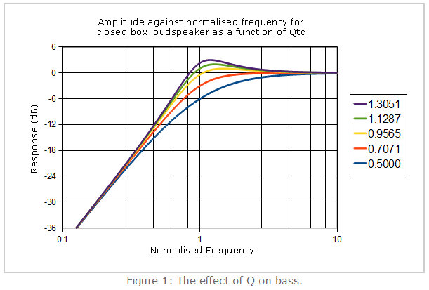
Bigger box and you are overdamped, the blue line essentially, with deep bass but lousy power handling.
100L seems a lot even for two drivers. Might be better with transmission line.
Every closed box builders knows this formula by heart... or should... 😀
Vtc = Vas / ((Qtc ^ 2/Qts ^ 2) - 1)
For Qtc = 0.7 and Qts = 0.5 it comes out at the Vas for maximally flat (orange) BW2.
Bigger box and you are overdamped, the blue line essentially, with deep bass but lousy power handling.
100L seems a lot even for two drivers. Might be better with transmission line.
Last edited:
Morning Steve and Jaco
These 404's seem mighty odd to me having the appearance and size of the Studio 3's MKII bar the cabinet design. I've only recently become aware of the 101,202,303 and 404 series. I'd be interested in seeing a photo of the crossover to compare with the Studio 3's.
The 8DC441's definitely need a Zobel to tame the peaks in the upper mids - something in the region of a 5uF cap and 15 Ohm resistor.
They work very well in the Studio 3 cabinets as a TL but can't comment on how they work in the 404 cabinet as I've never heard them.
Cheers
Mark
Thank you for the feedback Mark.
These were South Africa specific afaik. One of the distributors bought up a huge quantity of the drivers from TDL before they went bust and then built a standard ported enclosure to "match", but not to the fullest potential of these drivers.
That's why I want to build copies of the Studio 3 cabinets - it's just that I cannot find any information online.
So my next option will be sealed.
The crossover is bog standard; see below.
Attachments
Last edited:
Just to add, Jaco ..have you tried repositioning them? I know with the Studio 3's, if you get within 0.5m of walls, particularly the side walls, the sound esp bass, can change quite a bit (other room factors affecting too obviously). I have managed before to negate this by keep moving the speakers distance and tow-in a little at at time when space is limited but it's much easier if you can clear rear and side walls by over 0.5m.
These cabinets have back firing ports, no bigger than 50mm I would guess.
The upper driver also seems to be isolated from the rest of the cabinet; basically in its own enclosure with its own port.
Apologies for the bad quality of the photo, but this is what they look like:
Attachments

100L seems a lot even for two drivers. Might be better with transmission line.
Using 2 drivers in TL makes the calculations a bit more complicated?
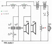
Studio 3
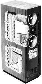
The attachment shows the internal structure of the Studio 3 ..not sure if that would be enough to work from?
I believe this is the first version with the crossover behind the woofer but later versions had the crossover attached to the back of the junction box on the back afaik. I can't imagine they changed the internal structure though.
Attachments
Last edited:
Using 2 drivers in TL makes the calculations a bit more complicated?
Not really, assuming they're physically close together; the line just 'sees' a single exciting force with the centre being the centre-point between the two drivers. It only gets more complex if the drivers are spaced significantly apart.
Morning Steve, may your joy spread to us all 🙂 That has to be a contender for the first Thiele/Small related formulas I learned.Morning, closed box fans! 😎
Every closed box builders knows this formula by heart... or should... 😀
Vtc = Vas / ((Qtc ^ 2/Qts ^ 2) - 1)
The next was fs, the box size changes it. 0.7 always comes out with the lowest f3
Here showing 0.5 0.7 and 0.9 from the same speaker in different boxes.
Attachments
The attachment shows the internal structure of the Studio 3 ..not sure if that would be enough to work from?
I believe this is the first version with the crossover behind the woofer but later versions had the crossover attached to the back of the junction box on the back afaik. I can't imagine they changed the internal structure though.
This is what I also found, but I need the physical measurements of the transmission line, etc. 🙂
- Home
- Loudspeakers
- Multi-Way
- TDL Studio 3 speaker repair/restoration