I have a few questions on building an amp using TDA7393.
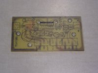
I am starting with the application circuit from the documentation attached.
I will be using in stereo mode and have no need to use the chips mute or st-by functionality. This doesn't have to sound spectacular, but I would like it to be as good as possible.
1. I understand that the round capacitors where the polarity is designated are to be electrolytic. Should they be any special kind of electrolytic?
2. What kind of caps are the ones represented by a rectangle? Ceramic disc?
3. Are there any components I can disregard since I won't be using mono, mute, or st-by?
4. Depending on answer to #3: Do I need to tie the st-by pin to +5vdc to have the amp operational? What about mute pin(s)...tie to ground, 12vdc, 5vdc?
Attachments
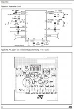
The caps drawn as rectangles are non polarised such as polystyrene or polyester etc. You won't find ceramics in those values I would imagine (1uf).
C3 and C4... can't see why an electroylitic won't be OK... just choose good quality parts such as 105 degree rating low E.S.R. types.
Am guessing that for the mute function to be active require the transistor/s to turn on in which case if not needed just omit R1 and R2 but keep the caps of course.
C3 and C4... can't see why an electroylitic won't be OK... just choose good quality parts such as 105 degree rating low E.S.R. types.
Am guessing that for the mute function to be active require the transistor/s to turn on in which case if not needed just omit R1 and R2 but keep the caps of course.
Thanks, I was thinking they should probably be polyester film after I posted.
Should any other caps be low ESR, like the main filter cap C1?
Also, what voltage rating should I be looking for for the caps?
Should any other caps be low ESR, like the main filter cap C1?
Also, what voltage rating should I be looking for for the caps?
Low ESR types are so common these days I personally wouldn't use anything else. So that includes C1 of course... and you might find 4700uf a more common value.
Choose a voltage rating that gives a reasonable safety margin. For a 12 volt supply, 16 volts caps are fine, if it's nearer 14 or 15 volts then go for 25 volt working.
Choose a voltage rating that gives a reasonable safety margin. For a 12 volt supply, 16 volts caps are fine, if it's nearer 14 or 15 volts then go for 25 volt working.
OK, I will go low ESR on all of them.
I will preferably be running 12vdc however I want the ability to play around with different supplies if need be, so I will choose a 25v rating.
Is carbon film ok for the resistors in this circuit or should I go with metal film?
I will preferably be running 12vdc however I want the ability to play around with different supplies if need be, so I will choose a 25v rating.
Is carbon film ok for the resistors in this circuit or should I go with metal film?
5% carbons are fine... lol 20% pieces of wet string are fine, as those three resistors have no audio on them 🙂
The main advantage of metal film is long term stability (the noise level is lower but you would be hard pushed to say it made an audible difference in 99.9% of designs)
The main advantage of metal film is long term stability (the noise level is lower but you would be hard pushed to say it made an audible difference in 99.9% of designs)
5% carbons are fine... lol 20% pieces of wet string are fine, as those three resistors have no audio on them 🙂
The main advantage of metal film is long term stability (the noise level is lower but you would be hard pushed to say it made an audible difference in 99.9% of designs)
Great, that's what I figured. I think it's about time to order some parts and etch a pcb. I've assembled amp kits before but this will be my first scratch build. Should be fun.
Hi,
Just a quick observation, you say you don't need the mute. Are you planning to use relays to mute the speakers at power up as if you don't use the mute those amps are likely to make quite a thump at power on. I would put an RC circuit on them to mute the amplifer for the first few seconds after turn on.
Regards,
Andrew
Hi,
Just a quick observation, you say you don't need the mute. Are you planning to use relays to mute the speakers at power up as if you don't use the mute those amps are likely to make quite a thump at power on. I would put an RC circuit on them to mute the amplifer for the first few seconds after turn on.
Regards,
Andrew
Thanks, that is definitely somthing I'll be looking out for. I plan to make my proto pcb with space for all components so I will be able to test this kind of scenario.
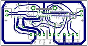
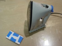
Ready to transfer:

Who says ironing is just for the ladies?

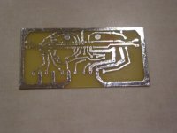
Takin' a ride on the o'le hot/stir plate. It's etch-tastic!

Not bad, but the generic photo paper works a lot better than the ultra super premium Epson brand photo paper I used this time. What a pain it was to remove!

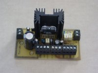
Tinned. Turned out OK. Only needed one solder bridge.

It's drill time...more to come...
Who says ironing is just for the ladies?
Takin' a ride on the o'le hot/stir plate. It's etch-tastic!
Not bad, but the generic photo paper works a lot better than the ultra super premium Epson brand photo paper I used this time. What a pain it was to remove!
Tinned. Turned out OK. Only needed one solder bridge.
It's drill time...more to come...
Attachments


Tried the glossy magazine page myself, and WAY cheaper than photo paper.
Just use a page with lots of white space on it.
Just use a page with lots of white space on it.
Test Results.
The Good:
1. It works!
2. Sounds pretty good.
3. Amp is operational when ST-BY is tied to source voltage.
4. Amp is operational when mute is floating.
5. Mute1 and Mute2 components can be removed from the circuit without affecting the amplifier.
The Bad:
1. I want to use this with a PC while using the 12V from the PC power supply. The PC I tried seems to have a noisy supply. I am working around it now by using a separate cheap ole power supply. More testing will be done with other power supplies.
2. The fixed gain for the TDA7393 is too much for the output of the typical PC sound card. I don't want to use a volume pot as I plan to control the volume from the PC. I need to attenuate the input signal I think.
Question:
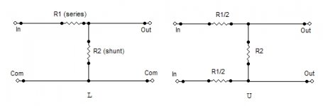
I assume I can use resistor(s) to attenuate the input signal. From research I believe I need two resistors for each input? One won't work for some reasons. Do I need to set it up according to the attached diagram? (figure L)

The Good:
1. It works!
2. Sounds pretty good.
3. Amp is operational when ST-BY is tied to source voltage.
4. Amp is operational when mute is floating.
5. Mute1 and Mute2 components can be removed from the circuit without affecting the amplifier.
The Bad:
1. I want to use this with a PC while using the 12V from the PC power supply. The PC I tried seems to have a noisy supply. I am working around it now by using a separate cheap ole power supply. More testing will be done with other power supplies.
2. The fixed gain for the TDA7393 is too much for the output of the typical PC sound card. I don't want to use a volume pot as I plan to control the volume from the PC. I need to attenuate the input signal I think.
Question:
I assume I can use resistor(s) to attenuate the input signal. From research I believe I need two resistors for each input? One won't work for some reasons. Do I need to set it up according to the attached diagram? (figure L)
Attachments
Cool, I want to build one and run it through the wringer and see how it stands up to the ol' maytag . jer
As in the left diagram will be fine. Try to keep R1 at around 22k and select R2 accordingly.
Keeping them low helps prevent HF roll off due to input capacitance. It helps with noise to but that's little more than theoretical here.
Keeping them low helps prevent HF roll off due to input capacitance. It helps with noise to but that's little more than theoretical here.
As in the left diagram will be fine. Try to keep R1 at around 22k and select R2 accordingly.
Keeping them low helps prevent HF roll off due to input capacitance. It helps with noise to but that's little more than theoretical here.
Thanks. By "select R2 accordingly" do you mean by trial and error or is there a formula to give me R2 based on R1 at 22k and what db level I would want to attenuate?
- Status
- Not open for further replies.
- Home
- Amplifiers
- Chip Amps
- TDA7393 design help