@cmorariu
You partly are right. With small signals there are no alinearities at all. But keep in mind that the amp signal in that case is (Zsync + Zload )/Zload times the load/speaker signal due to the voltage divider. The feed back loop of course takes care that the output equals the desired amplification at the load, including the required output impedance of the whole amp.
But. Imagine a max. triangle signal with nearly the slew rate of the chipamp. The largest part of it, the output follows the output of the amp via the transistors. But across the zero point, the voltage divider gets active. This means that across this point the slope of the output of the amp must rise or fall (Zsync + Zload )/Zload times quicker than the voltage over the load itself. And here it goes wrong, because the amp is on (and even over) its maximum slope. This will introduce alinearities around the crossing point i.e. cross over distortion. I cannot make it better.
Hence, diverse autors advocate the far more complicated and less stable solution. But, with a small sync resistor this distortion due to the maximum slew rate of the amp can greatly be avoided. And with a 2A max current, the amp still remains in its lower working area and therefore in its lower distortion area at a total output power, more than specified for the chip alone. So, the construction will really improve the performance, but only with a low value of the sync resistor.
For a bass booster this counts less, because you will not reach the maximum slew rate.
P.S. I question myself why the pair TIP35/36C is not used. They are very cheap, handle 25A continuous, 125W, hFE = 15, and 100V. More suitable with low impedance loads.
Last edited:
The step change...................For a bass booster this counts less, because you will not reach the maximum slew rate..................
should happen instantaneously. You explained it correctly earlier.At the cross over point the amp has to jump over from -0,7V to +0,7V
The bass frequency does not change the requirement that the amp "crosses over" at that step change.
This requires an infinite slew rate. Clearly no amplifier has the capability to slew infinitely fast.
@zanden30 I like your triangle representation! It is right and intuitive, and yes, slew rate of the output must be (Zsync+Zload)/Zload times faster near crossover. I tested the amp (5.1ohm sync, 0.1ohm in emitters) between 40Hz and 30KHz, +/-47V, on a 4ohm load at full power just below the limit of clipping. Sine wawe is pure without any visible distortion at all frequencies.
Keep in mind that slew rate can be also load dependent and most probably is faster at crossover when load decreases.
Most problematic is the behaviour of the circuit at the top of your triangle. If you look at transistor's datasheet, Ube increases drastically with Ic. At above 10A Ube can go up to 1.5V (2V for TIP35). Also the voltage on emitter resistor becomes significant, 1.5V at 10A. In conclusion the voltage on SYNC resistor to drive the transistor becomes about 3V, more than three times the one computed near crossover. Add the drastic decrease of Hfe of the transistor, it can go as low as 10, another 1A on TDA exit to feed the base of transistor. So if you start with 2A over the SYNC you end up by asking 7A from TDA at full output voltage!
About TIP35, only TIP35C is acceptable because of Vce. In terms of Hfe, Ube and safe operating area is quite similar. For low impedance loads, it might be a better choice due to it's increased current capability.
@AndrewT and CMORARIU
@AndrewT:
Without the sync resistor you are right, then a jump of 1,4 V in an infinite small time is necessary. And there allways remains cross over distorion.
But with the sync R, only the output SR times the multiplication factor is needed for the amp. And that means, that with lower frequency, say 1.000 Hz at max volume, the required Slew Rate is only 1/20 of the requirment that I calculated. So 🙂 no problem.
@CMORARIU:
Thanks for your impicit compliments....
1. 1% distortion of a sinus is invisible with a scoop! So that is not a prove that R=5,1 Ohm is the right choice.
2. The specified SR in the datasheet will be the maximum available. So it can only grow worse.....
3. You are right with the clipping conditions at the tops of the triangle. This requires in this design a somewhat higher rail voltage.
4. You are also right that at the top the current from the LM of TDA will be in the range of 7A, due to Vbe of the power transistor. But than the output current to the load has more than doubled and the power times 4, a very good improvement. You could dismiss the emitter resistors , which are not necessary (if you do not double or tiple the power transistors for even more boosting). And use transistors with higher hFE, like Dr Frost did, but their limit is 15A. A 0,6 Ohm sync R is a good compromise. A darlington will make it worse, alas, due to the even higher Vbe.. There is no easy ideal solution, I fear.......😡
I still am interested in real measurements with an analyser.
In the real word nothing is ideal, everybody knows. Dr Frost indicated a simple to build, affordable and rewarding circuit in terms of price+work/quality. It's not the best amp nor the highest fidelity one. It just sounds good, drives lower impedances than the bare TDA it employes and seems to be reliable. It is not my amp of choice but I gave it a chance to play with and I can assure you that it works as described.
I could not agree more!
I was just frustrated that a mathematical-electronic calculation/justification of the amp lacked.
Now I am sure it is also from theoretical point of view a very good idea of Dr Frost, especially when you choose the Rsync < 1 Ohm.
I was just frustrated that a mathematical-electronic calculation/justification of the amp lacked.
Now I am sure it is also from theoretical point of view a very good idea of Dr Frost, especially when you choose the Rsync < 1 Ohm.
There is no attachment in post1.
There is no Rsync in post 1.
There are two links, one to Facebook, the second to maemo.org, neither of which has any connection to DIYaudio,
Why should Members of DIYaudio need to register with either of these other organisations to get to the schematic being discussed here on our Forum?
There is no Rsync in post 1.
There are two links, one to Facebook, the second to maemo.org, neither of which has any connection to DIYaudio,
Why should Members of DIYaudio need to register with either of these other organisations to get to the schematic being discussed here on our Forum?
Last edited:
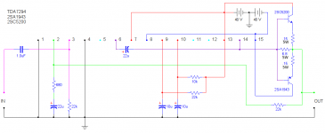
At the top of the first page you find this text:
" if you use other transistors you may need to experiment with another value for the SYNC resistor." and also the picture. You do not need to click on a link.
" if you use other transistors you may need to experiment with another value for the SYNC resistor." and also the picture. You do not need to click on a link.
I had the same problem when using an open wifi connection. The site where the files are located requires a secure connection.
Attachments
Last edited:
Great, I did not know that security issue. It is the right scheme/figure.
Note that the two 0,15 Ohm resistors in the emitter can be withdrawn and the 6,8 Ohm should be something like 0,3 or 0,6 Ohm as I calculated previously in this thread in order to proceed high frequencies in maximum volume.
Note that the two 0,15 Ohm resistors in the emitter can be withdrawn and the 6,8 Ohm should be something like 0,3 or 0,6 Ohm as I calculated previously in this thread in order to proceed high frequencies in maximum volume.
I can see Mark's attachment in post453.
Which resistor is Rsync?
0,15 Ohm is easily read and unambiguous.
Look at what you inserted into the sch.
Which resistor is Rsync?
0,15 Ohm is easily read and unambiguous.
Look at what you inserted into the sch.
TDA7293 + 4Transistors
I tested today Dr. Frost circuit adding one more pair of 2SC5200 and 2SA1943.
My intention is to build a bridged amplifier delivering 500W / 4ohm.
For now I built just one half of the bridged amp, and spent some time to make some measurements. This is the test prototype:
http://www.diyaudio.com/forums/<a href=
Delivered RMS power is 19.2x19.2 / 1.7 = 216 W. At this power FFT is:
http://www.diyaudio.com/forums/<a href=
Same fidelity! At 30Khz - same. Distortions predicted by skeptics appear over 40-45Khz due to TDA's limited slew rate. Look what happened at 50Khz
http://www.diyaudio.com/forums/<a href=
- Home
- Amplifiers
- Chip Amps
- TDA7294 + Power Transistors AMP (TDA7293 to come also)